Table of Contents
Advertisement
Quick Links
Advertisement
Table of Contents

Summary of Contents for EnaSolar immerSUN
- Page 1 ® I n s t a l l a t i o n a n d U s e r G u i d e...
-
Page 2: Table Of Contents
View Readings Advanced Settings External Boost Input Multifunctional Relay Installation System Overview immerLINK Linking Units immerSUN at a Glance Electrical Connections Sensor Installation Setup EnaSolar Monitoring and Reporting Configuring an EnaSolar Site Wiring Diagrams Wiring: Single Heater Wiring: Two Heater Wiring: Three Heater Wiring: Underfloor Heating (opt. -
Page 3: Introducing The Immersun
The power going to the load is a non-distorted true sine wave, only the voltage is altered. This control technology is unique to the immerSUN and is more sophisticated than any similar product on the market. TruSine™ technology ensures trouble free operation with all inverters and compatibility with all import/export energy monitors. -
Page 4: Main Screen
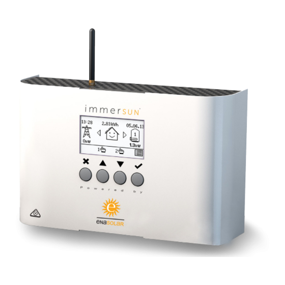
Main Screen The main screen shows the status of the immerSUN, the imported or exported power, the date and time and the savings made today. The house in the centre of the screen will be ‘happy’ if no power is being imported, otherwise a straight face will be displayed. -
Page 5: Savings
Today, this Week, this Month and this Year as well as the Total since the immerSUN has been installed. The savings can be displayed as a list or in a graph. The savings are shown in kWh as well as financially in the chosen currency. For the financial savings to be correct, the user must keep the tariff up to date. -
Page 6: Boost (Manual)
Boost (Manual) A heater can be ‘boosted’ to fuII power for a short period regardless of the amount of available export power, this function is called Manual Boost and is activated from the main screen. Once the boost starts, the remaining boost period will be displayed, this will start at 1 hour but can be adjusted during the boost. -
Page 7: Boost (Timed)
Boost (Timed) The immerSUN can be programmed to ‘boost’ the heating for each heater at certain times. Boost means that the heater will be at full power regardless of the amount of available export power. This means that power may be drawn from the mains grid supply during boost times. -
Page 8: Menu
18.30-19.30 MTWTFSS - available. Holiday Mode MAIN MENU HOLIDAY MODE The immerSUN can be set to Holiday Mode, when you are away from Savings Press to put unit in home. This will stop the immerSUN standby. - Page 9 View Configuration to be entered to This screen gives an overview access the menu. RELAY FUNCTION of the immerSUN configuration. When heating If the Advanced It is useful to check the current Settings menu is settings. Include Boost...
-
Page 10: View Readings
View Readings This screen shows various readings and other information. See the list below for a description of the readings. This screen is useful for diagnosing installation issues. Title Description MAIN MENU Version: Firmware version number and hardware type View Readings Serial No: Serial number of the unit Input V:... -
Page 11: Advanced Options
Advanced Options... -
Page 12: Advanced Settings
50W to ensure that the electricity meter does Press then use not register any import when the to make changes. immerSUN is diverting energy. Check Period CHECK PERIOD This is the time between checking Period: 15 min... -
Page 13: External Boost Input
This is an external input which can be used to trigger a boost or enable/disable heater outputs. The External Boost input is the 2-terminal connector labelled EX BST. Any AC voltage from 24V to 240V present on these terminals will be recognised by the immerSUN. MAIN MENU... -
Page 14: Relay Settings
Multfunction The heater will NOT be boosted Relay Settings by the immerSUN but will heat as The settings for the normal. Instead an auxiliary boiler will be called to boost. Multifunction Relay... -
Page 15: Multifunctional Relay
The Multifunction Relay is a relay that can be used for many different purposes. The operation is controlled by the immerSUN and will operate when certain conditions are met, these conditions can be user defined. The relay can be used to control pumps, send signals to the boiler and switch on/off appliances etc. -
Page 16: Installation
Legionella control. This is an ideal application for the External Boost input. The immersion heater should ONLY be connected to the immerSUN, do not connect the immersion heater to the heat pump or solar thermal controller. - Page 17 The immerSUN and the Sensor Clamp must be on the SAME PHASE. If the generation is 3-phase, an immerSUN can be used on each phase, if only one or two immerSUN’s are used, only one-third or two-thirds of the surplus power will be able to be...
-
Page 18: System Overview
System Overview PV ARRAY ELECTRICITY GRID INVERTER SENSOR CLAMP DISTRIBUTION BOARD SUPPLY METER OTHER LOADS Wireless Sensor option available (uses immerLINK IMMERSUN PV HOT WATER CONTROLLER WATER HEATER (or other heater) -
Page 19: Immerlink Tm Linking Units
(Linking Units) immerLINK™ is a wireless network used by immerSUN devices. Up to 5 immerSUN units can be ‘linked’ together by using immerLINK™. Linking several units enables more export power to be consumed, with each device being able to control a 3kW load, up to 15kW of would-be exported power can be utilised. Use the immerLINK Search option in the Advanced Menu to link devices. -
Page 20: Immersun At A Glance
Glance External overview 1) LCD display 2) Control buttons 3) Cover (removable) 4) Cover screws... - Page 21 Cover and Bottom Panel Removed 1) Sensor Clamp 7) EX BST – External Boost input 2) LINE – mains supply input 8) Mounting holes 3) HEATER 1 9) Cable anchor points 4) HEATER 2 10) Antenna connector 5) RELAY – Multifunction Relay 11) Bottom panel (removable) 6) Cooling fan 12) Bottom panel screws...
-
Page 22: Electrical Connections
Electrical Connections The electrical connections are made by the pluggable screw terminals. See Wiring Diagrams section and choose the most appropriate wiring scheme for the installation. HEATER 1 RELAY SENSOR LINE HEATER 2 EX BST Cable Anchors Plug-in Screw Terminals Important! ●... -
Page 23: Sensor Installation
(NOT the PV generation meter). Clamp the sensor around the LIVE from the meter. Ensure the clamp is securely closed around the cable. It does not matter which way round the sensor is clamped around the cable, the immerSUN will work out the import/export direction automatically. -
Page 24: Setup
The immerSUN requires an initial set-up to ensure that the direction of grid power (import and export) is correctly registered by the unit. To achieve this, a resistive load must be connected to Heater 1 on the immerSUN and must be turned on for the 2-5 minutes that it takes to complete the configuration. - Page 25 Setting up an ImmerSUN when not using heater outputs When there is a requirement to use only the multi-function relay, the immerSUN still requires initial configuration so that the grid power direction (import and export) is correctly registered by the unit.
-
Page 26: Enasolar Monitoring And Reporting
EnaSolar Monitoring and Reporting ENASOLAR INVERTER WIFI LINK ENASOLAR CAT 6 ROUTER ETHERNET BRIDGE WIFI LINK RADIO LINK (NOT WIFI) ENASOLAR REPORTING PV HOT WATER AND MONITORING CONTROLLER... -
Page 27: Configuring An Enasolar Site
7. Connect the EnaSolar Ethernet Bridge (RJ45/CAT6) to the home network/router and to the power. 8. Set up in the immerSUN Controller - Tariff - Set Currency to $. Set tariff to the cost of your power. 9. Set up in the immerSUN Controller - Advanced Settings... - Page 28 ● FOUND/FINDING CONNECTION - The inverter is able to talk to the Ethernet Bridge but the bridge is unable to talk to the immerSUN Controller. Retry Step 9 and 10. ● CONNECTED - Success. ● COMMS ERROR - There is an issue with the internal communications of Inverter’s Display.
-
Page 29: Wiring Diagrams
Wiring Diagrams... DISCLAIMER: These wiring diagrams show typical examples. It is up to the installer to ensure the installation conforms to the appropriate wiring regulations and network connection standards. -
Page 30: Wiring: Single Heater
Wiring: Single Heater RELAY IMMERSUN SUPPLY LOAD ISOLATOR ISOLATOR 3.2kW max. L N E 220-240VAC SUPPLY HEATER AND THERMOSTAT... - Page 31 This is the most simple installation and the most common. One heater is wired to the Heater 1 output. The heater is heated with surplus power until the thermostat opens, the immerSUN will then display HOT. The surplus power will then be exported until the thermostat closes and heating will resume. Isolators The isolators shown may not be required but there should always be a way of isolating the supply, e.g.
-
Page 32: Wiring: Two Heater
Wiring: Two Heater RELAY IMMERSUN SUPPLY LOAD ISOLATOR ISOLATORS 3.2kW max. L N E 220-240VAC SUPPLY HEATER AND THERMOSTAT 3.2kW max. HEATER AND THERMONSTAT... - Page 33 After a few seconds, (providing export power is still available), Heater 2 will start to be heated. If Heater 2 reaches maximum temperature, the display will show HOT and the immerSUN will switch back to Heater 1. During heating of the lower priority heater, the immerSUN will switch to the higher priority heater periodically to check if it can take more heat.
-
Page 34: Wiring: Three Heater
Wiring: Three Heater HEATER AND THERMONSTAT 3.2kW max. LOAD ISOLATOR RELAY IMMERSUN LOAD SUPPLY ISOLATORS ISOLATOR HEATER AND THERMOSTAT 3.2kW max. 3.2kW max. L N E 220-240VAC SUPPLY 3.2kW max. 3.2kW max. HEATER AND THERMONSTAT... - Page 35 If Heater 2 reaches maximum temperature, the display will show HOT and the immerSUN will switch the relay over so that Heater 3 can be heated. During heating of a lower priority heater, the immerSUN will switch to the higher priority heater periodically to check if it can take more heat.
-
Page 36: Wiring: Underfloor Heating (Opt. 1)
Wiring: Underfloor Heating (Opt. 1) 220-240VAC SUPPLY L N E SUPPLY ISOLATOR UFH MAT 3.2kW max. THEMOSTAT RELAY IMMERSUN SUPPLY LOAD ISOLATOR ISOLATOR HEATER AND THERMOSTAT 3.2kW max. L N E 220-240VAC SUPPLY... - Page 37 UFH thermostat is calling for heat. By utilising this wiring and configuration, the thermostat could be of any type, since it is only providing a signal input to the immerSUN, and does not form any part of the immerSUN variable voltage output circuitry.
-
Page 38: Wiring: Underfloor Heating (Opt. 2)
Wiring: Underfloor Heating (Opt. 2) UFH MAT 3.2kW max. THEMOSTAT L N E RELAY IMMERSUN LOAD SUPPLY ISOLATOR ISOLATOR HEATER AND THERMOSTAT 3.2kW max. L N E 220-240VAC SUPPLY... - Page 39 UFH thermostat is calling for heat. By utilising this wiring and configuration, the thermostat could be of any type, since it is only providing a signal input to the immerSUN, and does not form any part of the immerSUN variable voltage output circuitry.
-
Page 40: Wiring: Dual Tariff (Single Meter)
Wiring: Dual Tariff (Single Meter) 220-240VAC SUPPLY (off peak) SUPPLY ISOLATOR RELAY IMMERSUN LOAD SUPPLY ISOLATOR ISOLATORS HEATER AND THERMOSTAT 3.2kW max. L N E 220-240VAC 24 hr SUPPLY HEATER AND THERMOSTAT 3.2kW max. - Page 41 Dual Tariff Wiring – Single Meter It is simple to wire the immerSUN to handle dual rate tariffs when there is only one supply meter. The External Boost input can be used to detect when the economy rate electricity is available and automatically boost the heater output.
-
Page 42: Wiring: Dual Tariff (Two Meter)
Wiring: Dual Tariff (Two Meter) 220-240VAC SUPPLY (off peak) SUPPLY ISOLATOR RELAY IMMERSUN SUPPLY LOAD ISOLATORS ISOLATOR HEATER AND THERMOSTAT 3.2kW max. L N E 220-240VAC 24 hr SUPPLY HEATER AND THERMOSTAT 3.2kW max. - Page 43 If there are two meters at the property, for dual tariff metering, it is necessary to make sure that power is drawn from the correct meter. The immerSUN must be powered from a 24-hour supply and the heater must be connected directly to the immerSUN, however, during the economy tariff times, the heater needs to draw power from the economy tariff meter.
-
Page 44: Wiring: Pool Or Heatpump
Wiring: Pool or Heatpump POOL, SPA POOL, HEATPUMP OR OTHER NON-RESISTIVE LOAD (MAX 16A) RELAY IMMERSUN SUPPLY LOAD ISOLATOR ISOLATOR 3.2kW max. L N E 220-240VAC SUPPLY WATER HEATER AND THERMOSTAT... - Page 45 Pool, spa pool, heatpump or other non-resistive load wiring The heater is heated with surplus PV power until the thermostat opens, the immerSUN will then display HOT. The surplus PV power can then be used for a pool or heatpump or other non-resistive load by using the multifunctional relay.
-
Page 46: Error Messages
Test: The heater can be tested by measuring the L – N resistance, it should be between 17Ω and 350Ω. Note: The immerSUN MUST BE OFF for this test. SENSOR ERROR ERROR 4 The sensor is giving unusual readings. - Page 47 UNIT OVERHEAT ERROR 6 The unit is overheating. UNIT OVERHEAT Check: There is adequate ventilation and that the vents are not blocked. Check: Ventilation OUTPUT OVERLOAD ERROR 7 The output current is too high. The heater OUTPUT OVERLOAD connected is too large. Check: The heater KW rating, it should be less than Check: 3.2kW and more than 150W.
-
Page 48: Technical Specifications
Technical Specifications Model Number: T1060 Supply Voltage: 220 – 240V AC @ 50Hz MCB/Fuse Rating: 16A / 13A Input Current (max): Load Capacity: 150W – 3200W Output Voltage: 0V – Supply Voltage Relay Contact Rating: 16A 250V AC External Boost Input: 24 –... -
Page 49: Site Installation Details
Site Installation Details Installed By: Installation Date: PV Panel Type and Size: PV Panel Quantity, String 1: PV Panel Quantity, String 2: Inverter Type/Model No.: Inverter Size: Inverter Serial No:... -
Page 50: Immersun Controller Details
ImmerSUN Controller Details Serial No: Heater 1: Heater 2: Multifunction Relay:... -
Page 51: Notes
Notes... - Page 52 ® EnaSolar Limited 66 Treffers Road Christchurch 8042 New Zealand Telephone 64 3 366 4550 Facsimile 64 3 366 0884...
Need help?
Do you have a question about the immerSUN and is the answer not in the manual?
Questions and answers