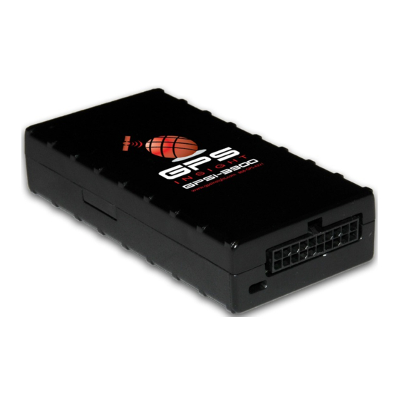
Summary of Contents for GPS Insight GPSI-3900
- Page 1 GPSI-3900 Installation Guide Internal Antenna Only www.gpsinsight.com 866.GPS.4321 support@gpsinsight.com...
- Page 2 The ground line (black wire) must be connected to chassis ground. Placement of the GPS device is critical to proper operation of the GPSI-3900. Find a discreet location for the placement of the tracker. The tracker has an internal GPS antenna and requires the device have a clear view to the sky.
- Page 3 Installation (continued) Standard Wiring Harness: Red Wire = constant +12V White Wire = switched +12V (+12V w/ ignition on, 0V w/ ignition off) Black Wire = ground Page 3 www.gpsinsight.com 866.GPS.4321 support@gpsinsight.com...
- Page 4 Installation Verification Upon successful installation of a GPSI-3900 both the GPS and Cellular lights will remain on. There are 2 LEDs on the back of the device, solid green (GPS) and solid amber (Cellular) indicate a good GPS and Cellular fix. A flashing GPS or Cellular light indicates that the GPSI-3900 is searching for the corresponding signal.
-
Page 5: Environmental Specifications
Electromagnetic Compatibility (EMC) EMC compliant for a ground vehicle environment SAE Test: SAE J1113 Parts 2, 12, 21 and 41 RF Connector The GPSI-3900’ s RF connector is SMC - the impedance is 50 Ohms nominal Page 5 www.gpsinsight.com 866.GPS.4321... -
Page 6: Physical Specifications
Environmental Specifications (continued) Operating Voltage Range The GPSI-3900 supports vehicles with 12 or 24 VDC systems including transients and electrical system noise; this includes ranges from 8.5 to 30 VDC SAE Test: SAE J1455 Transient Protection Input voltage transients typical of large trucks... -
Page 8: Customer Support
24/7/365 GPS Insight offers Customer Support Please contact us today if you have any additional questions about this product. 1.866.477.4321 Toll Free: support@gpsinsight.com Email: www.gpsinsight.com Web: www.gpsinsight.com 866.GPS.4321 support@gpsinsight.com...


Need help?
Do you have a question about the GPSI-3900 and is the answer not in the manual?
Questions and answers