Asus Motherboard P5PL2 User Manual
Asus p5pl2 motherboard user manual
Hide thumbs
Also See for Motherboard P5PL2:
- User manual (116 pages) ,
- Manual de démarrage rapide (38 pages)
Table of Contents
Advertisement
Advertisement
Table of Contents

Related Manuals for Asus Motherboard P5PL2


Summary of Contents for Asus Motherboard P5PL2
- Page 1 P5PL2...
- Page 2 Product warranty or service will not be extended if: (1) the product is repaired, modified or altered, unless such repair, modification of alteration is authorized in writing by ASUS; or (2) the serial number of the product is defaced or missing.
-
Page 3: Table Of Contents
Welcome! ... 1-1 Package contents ... 1-1 Special features ... 1-2 1.3.1 Product highlights ... 1-2 1.3.2 Innovative ASUS features ... 1-3 Chapter 2: Hardware information Before you proceed ... 2-1 Motherboard overview ... 2-2 2.2.1 Placement direction ... 2-2 2.2.2... - Page 4 Managing and updating your BIOS ... 4-1 4.1.1 Creating a bootable floppy disk ... 4-1 4.1.2 ASUS utility ... 4-2 4.1.3 ASUS CrashFree BIOS 2 utility ... 4-5 4.1.4 ASUS EZ Flash utility ... 4-7 4.1.5 ASUS Update utility ... 4-8 BIOS setup program ... 4-11 4.2.1...
- Page 5 5.2.3 Utilities menu ... 5-3 5.2.4 Manuals menu ... 5-5 5.2.5 Contact information ... 5-6 5.2.6 Other information ... 5-6 ASUS MyLogo™ ... 5-8 Appendix: CPU features Intel EM64T ... A-1 ® Enhanced Intel SpeedStep A.2.1 System requirements ... A-1 A.2.2...
-
Page 6: Canadian Department Of Communications Statement
Notices Federal Communications Commission Statement This device complies with Part 15 of the FCC Rules. Operation is subject to the following two conditions: • This device may not cause harmful interference, and • This device must accept any interference received including interference that may cause undesired operation. -
Page 7: Electrical Safety
Safety information Electrical safety • To prevent electrical shock hazard, disconnect the power cable from the electrical outlet before relocating the system. • When adding or removing devices to or from the system, ensure that the power cables for the devices are unplugged before the signal cables are connected. -
Page 8: About This Guide
Refer to the following sources for additional information and for product and software updates. ASUS websites The ASUS website provides updated information on ASUS hardware and software products. Refer to the ASUS contact information. Optional documentation Your product package may include optional documentation, such as warranty flyers, that may have been added by your dealer. -
Page 9: Conventions Used In This Guide
Conventions used in this guide To make sure that you perform certain tasks properly, take note of the following symbols used throughout this manual. DANGER/WARNING: Information to prevent injury to yourself when trying to complete a task. CAUTION: Information to prevent damage to the components when trying to complete a task. -
Page 10: P5Pl2 Specifications Summary
4-Step DRAM voltage control ASUS CrashFree BIOS 2 ASUS Q-Fan 4 Mb Flash ROM, AMI BIOS , PnP, DMI2.0, WfM2.0, SM BIOS 2.3, ASUS EZ Flash, ASUS CrashFree BIOS 2, ASUS MyLogo 1 x Parallel port 1 x Serial port... - Page 11 Chassis Intrusion CPU/Chassis/ Power Fan connectors Manageability WOL by PME, WOR by PME, Chassis Intrusion Support CD Drivers contents ASUS PC Probe II ASUS LiveUpdate Utility Anti-Virus software AI Booster Accessories 1 x IDE cable 2 x SATA cable 1 x SATA power cables for 2 SATA Devices...
- Page 13 This chapter describes the motherboard features and the new technologies it supports. Product introduction...
-
Page 14: Chapter Summary
Chapter summary Welcome! ... 1-1 Package contents ... 1-1 Special features ... 1-2 ASUS P5PL2... -
Page 15: Welcome
Thank you for buying an ASUS The motherboard delivers a host of new features and latest technologies, making it another standout in the long line of ASUS quality motherboards! Before you start installing the motherboard, and hardware devices on it, check the items in your package with the list below. -
Page 16: Special Features
Special features 1.3.1 Product highlights Intel LGA775 Pentium 4 CPU ® This motherboard supports the latest Pentium 4 CPU from Intel in LGA775 package. With 800/533MHz FSB, Hyper-Threading Technology and core- speeds up to 3.8GHz and beyond, Intelʼs LGA775 Pentium 4 is one of the fastest desktop processors to date. -
Page 17: Pci Express™ Interface
ROM chip. See page 4-5 for details. ASUS Q-Fan technology The ASUS Q-Fan technology smartly adjusts the fan speeds according to the system loading to ensure quiet, cool, and efficient operation. See page 4-34 for details. - Page 18 Chapter 1: Product introduction...
- Page 19 This chapter lists the hardware setup procedures that you have to perform when installing system components. It includes description of the jumpers and connectors on the motherboard. Hardware information...
- Page 20 Chapter summary Before you proceed ... 2-1 Motherboard overview ... 2-2 Central Processing Unit (CPU) ... 2-6 System memory ... 2-13 Expansion slots ... 2-16 Jumpers ... 2-19 Connectors ... 2-21 ASUS P5PL2...
-
Page 21: Before You Proceed
This is a reminder that you should shut down the system and unplug the power cable before removing or plugging in any motherboard component. The illustration below shows the location of the onboard LED. P5PL2 Onboard LED ASUS P5PL2 SB_PWR Standby Powered... -
Page 22: Motherboard Overview
Motherboard overview Before you install the motherboard, study the configuration of your chassis to ensure that the motherboard fits into it. Make sure to unplug the power cord before installing or removing the motherboard. Failure to do so can cause you physical injury and damage motherboard components. -
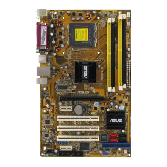
Page 23: Motherboard Layout
Top:Line In Center:Line Out Center:Line Out Below:Mic In Below:Mic In USBPW34 USBPW12 PCIEX1_2 RLT8111B SPDIF_OUT Audio PCIEX1_1 GAME FLOPPY AAFP ASUS P5PL2 18.8cm(7.5in) LGA775 Intel MCH 945PL PCIEX16 CLRTC CR2032 3V Lithium Cell CMOS Power PCI1 PCI2 SB_PWR PCI3 BIOS... -
Page 24: Layout Contents
2.2.4 Layout contents Slots 1. PCI-E x16 2. PCI-E x 1 3. PCI Jumpers 1. Clear RTC RAM (3-pin CLRTC) 2. USB Device wake-up (3-pin USBPW12, USBPW34, USBPW56, USBPW78) Rear panel connectors PS/2 mouse port (green) Parallel port LAN (RJ-45) port Line In port (light blue) Line Out port (lime) Microphone port (pink) - Page 25 System panel connector (20-1 pin PANEL) System power LED (Green 3-pin PLED) Hard disk drive activity LED (Red 2-pin IDE_LED) System warning speaker (Orange 4-pin SPEAKER) ATX power button/soft-off button (Yellow 2-pin PWRSW) Reset button (Blue 2-pin RESET) ASUS P5PL2 Page 2-23 2-24 2-25 2-26...
-
Page 26: Central Processing Unit (Cpu)
Contact your retailer immediately if the PnP cap is missing, or if you see any damage to the PnP cap/socket contacts/motherboard components. ASUS will shoulder the cost of repair only if the damage is shipment/ transit-related. •... - Page 27 The socket alignment key should fit into the CPU notch. ASUS P5PL2 Load plate Alignment key Gold triangle mark PnP cap This side of the socket box should...
- Page 28 The CPU fits in only one correct orientation. DO NOT force the CPU into the socket to prevent bending the connectors on the socket and damaging the CPU! Close the load plate (A), then push the load lever (B) until it snaps into the retention tab.
-
Page 29: Installing The Cpu Heatsink And Fan
CPU fan cable is closest to the CPU fan connector. Make sure to orient each fastener with the narrow end of the groove pointing outward. (The photo shows the groove shaded for emphasis.) ASUS P5PL2 Pentium ® ® Pentium D LGA775 heatsink and fan assembly comes in ®... - Page 30 Push down two fasteners at a time in a diagonal sequence to secure the heatsink and fan assembly in place. Connect the CPU fan cable to the connector on the motherboard labeled CPU_FAN. 2-10 Chapter 2: Hardware information...
-
Page 31: Uninstalling The Cpu Heatsink And Fan
To uninstall the CPU heatsink and fan: Disconnect the CPU fan cable from the connector on the motherboard. Rotate each fastener counterclockwise. Pull up two fasteners at a time in a diagonal sequence to disengage the heatsink and fan assembly from the motherboard. ASUS P5PL2 2-11... - Page 32 Rotate each fastener clockwise to ensure correct orientation when reinstalling. The narrow end of the groove should point outward after resetting. (The photo shows the groove shaded for emphasis.) Refer to the documentation in the boxed or stand-alone CPU fan package for detailed information on CPU fan installation.
-
Page 33: System Memory
Refer to the DDR2 Qualified Vendors List on the next page for details. • This motherboard does not support memory modules made up of 128 Mb chips or double sided x16 memory modules. ASUS P5PL2 Sockets DIMM_A1 and DIMM_A2 DIMM_B1 and DIMM_B2 2-13... - Page 34 Dual-channel memory configuration. Supports two pairs of modules inserted into the yellow and black slots as two pairs of Dual-channel memory configuration. Visit the ASUS website for the latest DDR2-533/400 MHz QVL. 2-14 Mode...
-
Page 35: Installing A Dimm
Support the DIMM lightly with your fingers when pressing the retaining clips. The DIMM might get damaged when it flips out with extra force. Remove the DIMM from the socket. ASUS P5PL2 DDR2 DIMM notch Unlocked retaining clip DDR2 DIMM notch 2-15... -
Page 36: Expansion Slots
Expansion slots In the future, you may need to install expansion cards. The following sub-sections describe the slots and the expansion cards that they support. Make sure to unplug the power cord before adding or removing expansion cards. Failure to do so may cause you physical injury and damage motherboard components. -
Page 37: Standard Interrupt Assignments
Onboard USB controller 2 Onboard USB controller 3 Onboard EHCI controller Onboard IDE port Onboard SATA port Onboard Audio controller Onboard LAN controller ASUS P5PL2 Standard Function System Timer Keyboard Controller Re-direct to IRQ#9 — Communications Port (COM1)* IRQ holder for PCI steering*... -
Page 38: Pci Slots
2.5.4 PCI slots The PCI slots support cards such as a LAN card, SCSI card, USB card, and other cards that comply with PCI specifications. The figure shows a LAN card installed on a PCI slot. 2.5.5 PCI Express x16 slot This motherboard supports PCI Express x16 graphic cards that comply with the PCI Express... -
Page 39: Clear Rtc Ram (Clrtc)
You do not need to clear the RTC when the system hangs due to overclocking. For system failure due to overclocking, use the C.P.R. (CPU Parameter Recall) feature. Shut down and reboot the system so the BIOS can automatically reset parameter settings to default values. ASUS P5PL2 Clear CMOS CLRTC Normal... - Page 40 USB device wake-up jumpers (3-pin USBPW12, USBPW34, USBPW56, USBPW78) Set these jumpers to +5V to wake up the computer from S1 sleep mode (CPU stopped, DRAM refreshed, system running in low power mode) using the connected USB devices. Set to +5VSB to wake up from S3 and S4 sleep modes (no power to CPU, DRAM in slow refresh, power supply in reduced power mode).
-
Page 41: Connectors
Line Out port (lime). This port connects a headphone or a speaker. In 4-channel, 6-channel, and 8-channel configuration, the function of this port becomes Front Speaker Out. Microphone port (pink). This port connects a microphone. ASUS P5PL2 SPEED LED Status Description... -
Page 42: Internal Connectors
Refer to the audio configuration table below for the function of the audio ports in 2, 4, 6, or 8-channel configuration. Audio 2, 4, 6, or 8-channel configuration Port 2-channel (Headset) Light Blue Line In Lime Line Out Pink Mic In USB 2.0 ports 3 and 4. -
Page 43: Ich7 Primary Ide Connector (40-1 Pin Pri_Ide)
IDE cable. • Use the 80-conductor IDE cable for Ultra DMA 100/66 IDE devices. P5PL2 IDE Connectors ASUS P5PL2 NOTE: Orient the red markings (usually zigzag) on the IDE ribbon cable to PIN 1. PIN 1... -
Page 44: Serial Ata Connectors
Serial ATA connectors (7-pin SATA1 [red], SATA2 [red], SATA3 [black], SATA4 [black]) These connectors are for the Serial ATA signal cables for Serial ATA hard disk drives. P5PL2 SATA Connectors Important notes on Serial ATA • You must install Windows Service Pack 1 before using Serial ATA hard disk drives. -
Page 45: Front Panel Audio Connector (10-1 Pin Aafp)
HD Audio or legacy ACʼ97 audio standard. P5PL2 Analog Front Panel Connector • We recommend that you connect a high-definition front panel audio module to this connector to avail the motherboard high-definition audio capability. ASUS P5PL2 CD(Black) Left Audio Channel Ground Ground Right Audio Channel... -
Page 46: Game/Midi Port Connector (16-1 Pin Game)
USB port connectors (10-1 pin USB56, USB78) These connectors are for USB 2.0 ports. Connect the USB/GAME module cable to any of these connectors, then install the module to a slot opening at the back of the system chassis. These USB connectors comply with USB 2.0 specification that supports up to 480 Mbps connection speed. -
Page 47: Cpu, Chassis, And Power Fan Connectors (4-Pin Cpu_Fan)
These are not jumpers! Do not place jumper caps on the fan connectors! P5PL2 Fan Connectors Only the CPU_FAN connector supports the ASUS Q-Fan feature. Chassis intrusion connector (4-1 pin CHASSIS) This connector is for a chassis-mounted intrusion detection sensor or switch. - Page 48 10. ATX power connectors (24-pin EATXPW, 4-pin ATX12V) These connectors are for ATX power supply plugs. The power supply plugs are designed to fit these connectors in only one orientation. Find the proper orientation and push down firmly until the connectors completely fit.
-
Page 49: System Panel Connector (20-1 Pin Panel)
ON turns the system OFF. • Reset button (Blue 2-pin RESET) This 2-pin connector is for the chassis-mounted reset button for system reboot without turning off the system power. ASUS P5PL2 SPEAKER PLED PANEL RESET... - Page 50 2-30 Chapter 2: Hardware information...
-
Page 51: Chapter 3: Powering Up
This chapter describes the power up sequence, the vocal POST messages, and ways of shutting down the system. Powering up... -
Page 52: Chapter Summary
Chapter summary Starting up for the first time ... 3-1 Powering off the computer ... 3-2 ASUS P5PL2... -
Page 53: Starting Up For The First Time
Two continuous beeps followed by four short beeps At power on, hold down the <Delete> key to enter the BIOS Setup. Follow the instructions in Chapter 4. ASUS P5PL2 Error Keyboard controller error Refresh Time error No master drive detected... -
Page 54: Powering Off The Computer
Powering off the computer 3.2.1 Using the OS shut down function If you are using Windows Click the Start button then click Shut Down... Make sure that the Shut Down option button is selected, then click the OK button to shut down the computer. The power supply should turn off after Windows If you are using Windows Click the Start button then select Turn Off Computer. -
Page 55: Chapter 4: Bios Setup
This chapter tells how to change the system settings through the BIOS Setup menus. Detailed descriptions of the BIOS parameters are also provided. BIOS setup... - Page 56 Chapter summary Managing and updating your BIOS ... 4-1 BIOS setup program ... 4-11 Main menu ... 4-14 Advanced menu ... 4-19 Power menu ... 4-30 Boot menu ... 4-35 Exit menu ... 4-40 ASUS P5PL2...
-
Page 57: Managing And Updating Your Bios
ASUS CrashFree BIOS 2 (Updates the BIOS using a bootable floppy disk or the motherboard support CD when the BIOS file fails or gets corrupted.) ASUS EZ Flash (Updates the BIOS in DOS mode using a floppy disk or the motherboard support CD.) ASUS Update (Updates the BIOS in Windows Refer to the corresponding sections for details on these utilities. -
Page 58: Afudos Utility
Windows 2000 environment ® To create a set of boot disks for Windows a. Insert a formatted, high density 1.44 MB floppy disk into the drive. b. Insert the Windows c. Click Start, then select Run. d. In the Open field, type D:\bootdisk\makeboot a: assuming that D is your optical drive letter. -
Page 59: Updating The Bios File
Updating the BIOS file To update the BIOS file using the AFUDOS utility: Visit the ASUS website (www.asus.com) and download the latest BIOS file for the motherboard. Save the BIOS file to a bootable floppy disk. Write the BIOS filename on a piece of paper. You need to type the exact BIOS filename at the DOS prompt. - Page 60 The utility verifies the file and starts updating the BIOS. A:\>afudos /iP5PL2.rom AMI Firmware Update Utility - Version 1.19(ASUS V2.07(03.11.24BB)) Copyright (C) 2002 American Megatrends, Inc. All rights reserved. WARNING!! Do not turn off power during flash BIOS Reading file ... done Reading flash ...
-
Page 61: Asus Crashfree Bios 2 Utility
4.1.3 ASUS CrashFree BIOS 2 utility The ASUS CrashFree BIOS 2 is an auto recovery tool that allows you to restore the BIOS file when it fails or gets corrupted during the updating process. You can update a corrupted BIOS file using the motherboard support CD or the floppy disk that contains the updated BIOS file. -
Page 62: Recovering The Bios From The Support Cd
Restart the system after the utility completes the updating process. The recovered BIOS may not be the latest BIOS version for this motherboard. Visit the ASUS website (www.asus.com) to download the latest BIOS file. Chapter 4: BIOS setup... -
Page 63: Asus Ez Flash Utility
4.1.4 ASUS EZ Flash utility The ASUS EZ Flash feature allows you to update the BIOS without having to go through the long process of booting from a floppy disk and using a DOS-based utility. The EZ Flash utility is built-in the BIOS chip so it is accessible by pressing <Alt>... -
Page 64: Asus Update Utility
4.1.5 ASUS Update utility The ASUS Update is a utility that allows you to manage, save, and update the motherboard BIOS in Windows allows you to: • Save the current BIOS file • Download the latest BIOS file from the Internet •... -
Page 65: Updating The Bios Through The Internet
Updating the BIOS through the Internet To update the BIOS through the Internet: Launch the ASUS Update utility from the Windows Start > Programs > ASUS > ASUSUpdate > ASUSUpdate. The ASUS Update main window appears. Select Update BIOS from... -
Page 66: Updating The Bios Through A Bios File
Updating the BIOS through a BIOS file To update the BIOS through a BIOS file: Launch the ASUS Update utility from the Windows clicking Start > Programs > ASUS > ASUSUpdate > ASUSUpdate. The ASUS Update main window appears. Select Update BIOS from a file option from the drop-down menu, then click Next. -
Page 67: Bios Setup Program
The BIOS setup screens shown in this section are for reference purposes only, and may not exactly match what you see on your screen. • Visit the ASUS website (www.asus.com) to download the latest BIOS file for this motherboard. ASUS P5PL2 4-11... -
Page 68: Menu Bar
Some of the navigation keys differ from one screen to another. 4-12 Configuration fields [11:51:19] [Thu 05/07/2004] [1.44M, 3.5 in] [ST320413A] [ASUS CD-S520/A] [Not Detected] [Not Detected] [Not Detected] [Not Detected] General help Use [ENTER], [TAB] or [SHIFT-TAB] to select a field. -
Page 69: Menu Items
4.2.9 General help At the top right corner of the menu screen is a brief description of the selected item. ASUS P5PL2 System Time [11:10:19] Use [ENTER], [TAB] System Date [Thu 03/27/2003] or [SHIFT-TAB] to Legacy Diskette A [1.44M, 3.5 in]... -
Page 70: Main Menu
[360K, 5.25 in.] [1.2M , 5.25 in.] [720K , 3.5 in.] [1.44M, 3.5 in.] [2.88M, 3.5 in.] 4-14 [11:51:19] [Thu 05/07/2004] [1.44M, 3.5 in] [ST320413A] [ASUS CD-S520/A] [Not Detected] [Not Detected] [Not Detected] [Not Detected] Use [ENTER], [TAB] or [SHIFT-TAB] to select a field. -
Page 71: Primary/Third/Fourth Ide Master/Slave
When set to [Disabled], the data transfer from and to the device occurs one sector at a time. Configuration options: [Disabled] [Auto] ASUS P5PL2 Select the type of device connected to the system. -
Page 72: 32Bit Data Transfer [Disabled]
PIO Mode [Auto] Selects the PIO mode. Configuration options: [Auto] [0] [1] [2] [3] [4] DMA Mode [Auto] Selects the DMA mode. Configuration options: [Auto] [SWDMA0] [SWDMA1] [SWDMA2] [MWDMA0] [MWDMA1] [MWDMA2] [UDMA0] [UDMA1] [UDMA2] [UDMA3] [UDMA4] [UDMA5] SMART Monitoring [Auto] Sets the Smart Monitoring, Analysis, and Reporting Technology. - Page 73 The Onboard IDE Operate Mode and sub-menu items appear only when the Configure SATA As item is set to [Standard IDE]. IDE Detect Time Out [35] Selects the time out value for detecting ATA/ATAPI devices. Configuration options: [0] [5] [10] [15] [20] [25] [30] [35] ASUS P5PL2 4-17...
-
Page 74: System Information
4.3.6 System Information This menu gives you an overview of the general system specifications. The BIOS automatically detects the items in this menu. AMIBIOS Version : 0107 Build Date : 09/08/05 Processor Type : Intel(R) Pentium(R) 4 CPU 2.66GHz Speed : 2666 MHz Count System Memory... -
Page 75: Advanced Menu
Manual - allows you to individually set overclocking parameters. Auto - loads the optimal settings for the system. Overclock Profile - loads overclocking profiles with optimal parameters for stability when overclocking. ASUS P5PL2 [Auto] Adjust system frequency/voltage. Select the targe CPU... -
Page 76: Dram Frequency [Auto]
The following item appears only when you set the AI Overclocking item to [Manual]. CPU Frequency [XXX] Displays the frequency sent by the clock generator to the system bus and PCI bus. The value of this item is auto-detected by the BIOS. Use the <+> and <->... -
Page 77: Fsb Termination Voltage [Auto]
The following item appears only when the AI Overclocking item is set to [Overclock Profile]. Overclock Options [Overclock 5%] Allows you to overclock the CPU speed through the available preset values. Configuration options: [Overclock 5%] ASUS P5PL2 [FSB888/DDR2-667] [Overclock 10%] [FSB960/DDR2-800] [Overclock 15%]... -
Page 78: Usb Configuration
4.4.2 USB Configuration The items in this menu allows you to change the USB-related features. Select an item then press <Enter> to display the configuration options. USB Configuration Module Version - 2.24.0-F.4 USB Devices Enabled: None USB Function Legacy USB Support USB 2.0 Controller The Module Version and USB Devices Enabled items show the auto-detected values. -
Page 79: Cpu Configuration
Allows you to disable or set to auto the CPU Internal Thermal Control function. Configuration options: [Auto] [Disabled]ss Hyper Threading Technology [Enabled] Allows you to enable or disable the Hyper Threading Technology. Configuration options: [Enabled] [Disabled] ASUS P5PL2 [Enabled] [Disabled] [Disabled] Sets the ratio... -
Page 80: Chipset
4.4.4 Chipset The Chipset menu allows you to change the advanced chipset settings. Select an item then press <Enter> to display the sub-menu. Advanced Chipset Settings Configure DRAM Timing by SPD Hyper Path 3 DRAM Throttling Threshold Booting Graphic Adapter Priority [PCI Express/PCI] PEG Buffer Length Link Latency PEG Root Control... - Page 81 Hyper Path 3 [Auto] Allows you to enable or disable the ASUS Hyper Path 3 feature. Configuration options: [Disabled] [Enabled] [Auto] DRAM Throttling Threshold [Auto] Enable DRAM Throttling Thermal Throttling will make your system more stable. Configuration options: [Disabled] [Auto] Booting Graphic Adapter Priority [PCI Express/PCI] Allows selection of the graphics controller to use as primary boot device.
-
Page 82: Onboard Devices Configuration
4.4.5 Onboard Devices Configuration Configure Win627EHG Super IO Chipset HD Audio Controller Onboard PCIEX GbE LAN LAN Option ROM Serial Port1 Address Parallel Port Address Parallel Port Mode ECP Mode DMA Channel Parallel Port IRQ Onboard Game/MIDI Port HD Audio Controller [Enabled] Allows you to enable or disable the high-definition audio CODEC. -
Page 83: Serial Port1 Address [3F8/Irq4]
Configuration options: [DMA0] [DMA1] [DMA3] Parallel Port IRQ [IRQ7] Configuration options: [IRQ5] [IRQ7] Onboard Game/MIDI Port [Disabled] Allows you to select the Game Port address or to disable the port. Configuration options: [Disabled] [200/300] [200/330] [208/300] [208/330] ASUS P5PL2 4-27... -
Page 84: Pci Pnp
4.4.6 PCI PnP The PCI PnP menu items allow you to change the advanced settings for PCI/PnP devices. The menu includes setting IRQ and DMA channel resources for either PCI/PnP or legacy ISA devices, and setting the memory size block for legacy ISA devices. - Page 85 IRQ-xx assigned to [PCI Device] When set to [PCI Device], the specific IRQ is free for use of PCI/PnP devices. When set to [Reserved], the IRQ is reserved for legacy ISA devices. Configuration options: [PCI Device] [Reserved] ASUS P5PL2 4-29...
-
Page 86: Power Menu
Power menu The Power menu items allow you to change the settings for the ACPI and Advanced Power Management (APM) features. Select an item then press <Enter> to display the configuration options. Suspend Mode Repost Video on S3 Resume ACPI 2.0 Support ACPI APIC Support APM Configuration Hardware Monitor... -
Page 87: Apm Configuration
Configuration options: [Everyday] [1] [2] [3]... ~ [31] RTC Alarm Hour To set the alarm hour, highlight this item and press the <+> or <-> key to make the selection. Configuration options: [00] [1]... ~ [23] ASUS P5PL2 [On/Off] [Power Off] [Disabled] [Disabled]... - Page 88 RTC Alarm Minute To set the alarm minute, highlight this item and press the <+> or <-> key to make the selection. Configuration options: [00] [1]... ~ [59] RTC Alarm Second To set the alarm second, highlight this item and press the <+> or <->...
-
Page 89: Hardware Monitor
• The CPU Q-Fan Control item appears with the default setting [Disabled]. • And the CPU Q-Fan Control item is enabled, the CPU Fan Profile Mode item appears with the default setting [Optimal]. ASUS P5PL2 [Disabled] [32.5ºC/90.5ºF] [36.0ºC/96.5ºF] [1864RPM] [Disabled]... - Page 90 (RPM). If the fan is not connected to the motherboard, the field shows N/A. CPU Q-Fan Control [Disabled] Allows you to enable or disable the ASUS Q-Fan feature that smartly adjusts the fan speeds for more efficient system operation. Configuration options: [Disabled] [Enabled] The CPU Fan Profile Mode item appears when you enable the CPU Q-Fan...
-
Page 91: Boot Menu
The number of device items that appears on the screen depends on the number of devices installed in the system. Configuration options: [xxxxx Drive] [Hard Drive] [ATAPI CD-ROM] or [Disabled] ASUS P5PL2 Specifies the Boot Device Priority Sequence. A virtual floppy disk... -
Page 92: Boot Settings Configuration
Allows you to enable or disable the full screen logo display feature. Configuration options: [Disabled] [Enabled] Set this item to [Enabled] to use the ASUS MyLogo™ feature. Add On ROM Display Mode [Force BIOS] Sets the display mode for option ROM. -
Page 93: Interrupt 19 Capture [Disabled]
If you forget your BIOS password, you can clear clear it by erasing the CMOS Real Time Clock (RTC) RAM. See section “2.6 Jumpers” for information on how to erase the RTC RAM. ASUS P5PL2 <Enter> to change password. <Enter> again to disabled password. -
Page 94: Change User Password
After you have set a supervisor password, the other items appear to allow you to change other security settings. Security Settings Supervisor Password User Password Change Supervisor Password User Access Level Change User Password Clear User Password Password Check User Access Level [Full Access] This item allows you to select the access restriction to the Setup items. -
Page 95: Clear User Password
Password Check [Setup] When set to [Setup], BIOS checks for user password when accessing the Setup utility. When set to [Always], BIOS checks for user password both when accessing Setup and booting the system. Configuration options: [Setup] [Always] ASUS P5PL2 4-39... -
Page 96: Exit Menu
Exit menu The Exit menu items allow you to load the optimal or failsafe default values for the BIOS items, and save or discard your changes to the BIOS items. Exit Options Exit & Save Changes Exit & Discard Changes Discard Changes Load Setup Defaults Pressing <Esc>... -
Page 97: Load Setup Defaults
Setup menus. When you select this option or if you press <F5>, a confirmation window appears. Select <OK> to load the default values. Select Exit & Save Changes or make other changes before saving the values to the non-volatile RAM.- ASUS P5PL2 4-41... - Page 98 4-42 Chapter 4: BIOS setup...
-
Page 99: Chapter 5: Software Support
This chapter describes the contents of the support CD that comes with the motherboard package. Software support... -
Page 100: Chapter Summary
Chapter summary Installing an operating system ... 5-1 Support CD information ... 5-1 ASUS MyLogo™ ... 5-8 ASUS P5PL2... -
Page 101: Installing An Operating System
The contents of the support CD are subject to change at any time without notice. Visit the ASUS website(www.asus.com) for updates. 5.2.1 Running the support CD Place the support CD to the optical drive. -
Page 102: Drivers Menu
5.2.2 Drivers menu The drivers menu shows the available device drivers if the system detects installed devices. Install the necessary drivers to activate the devices. Intel Chipset Drivers Installs the Intel ® Chipset Drivers. ADI Audio Driver Installs the ADI Audio Driver. Realtek Lan Driver ®... -
Page 103: Utilities Menu
This utility helps you keep your computer in healthy operating condition. ASUS Update Allows you to download the latest version of the BIOS from the ASUS website. Before using the ASUS Update, make sure that you have an Internet connection so you can connect to the ASUS website. -
Page 104: Asus Ai Booster
ASUS Ai Booster The ASUS AI Booster application allows you to overclock the CPU speed in a Windows ® environment. Anti-virus Utility The anti-virus application scans, identifies, and removes computer viruses. View the online help for detailed information. Chapter 5: Software support... -
Page 105: Manuals Menu
• Some user manuals listed in this menu may not be applicable for this motherboard model. Intel LGA775 CPU Install Userʼs Manual Allows you to open the Intel ASUS P5PL2 Acrobat Reader from the Utilities menu before ® ® LGA775 CPU installation guide. -
Page 106: Contact Information
5.2.5 ASUS Contact information Click the Contact tab to display the ASUS contact information. You can also find this information on the inside front cover of this user guide. 5.2.6 Other information The icons on the top right corner of the screen give additional information on the motherboard and the contents of the support CD. -
Page 107: Technical Support Form
Browse this CD Displays the support CD contents in graphical format. Technical support Form Displays the ASUS Technical Support Request Form that you have to fill out when requesting technical support. ASUS P5PL2... -
Page 108: Asus Mylogo
ASUS MyLogo™ The ASUS MyLogo™ utility lets you customize the boot logo. The boot logo is the image that appears on screen during the Power-On Self-Tests (POST). The ASUS MyLogo™ is automatically installed when you install the ASUS Update utility from the support CD. - Page 109 To launch the ASUS MyLogo™: Launch the ASUS Update utility. Refer to section “4.1.5 ASUS Update utility” for details. Select Options from the drop down menu, then click Next. Check the option Launch MyLogo to replace system boot logo before flashing BIOS, then click Next.
- Page 110 When the screen returns to the ASUS Update utility, flash the original BIOS to load the new boot logo. 10. After flashing the BIOS, restart the computer to display the new boot logo during POST. 5-10 Chapter 5: Software support...
-
Page 111: Appendix: Cpu Features
The Appendix describes the CPU features that the motherboard supports. CPU features... - Page 112 Chapter summary Intel EM64T ... A-1 ® Enhanced Intel SpeedStep Intel Hyper-Threading Technology ... A-3 ® Technology (EIST) ... A-1 ® ASUS P5PL2...
-
Page 113: A.2.1 System Requirements
32-bit operating systems. • The motherboard comes with a BIOS file that supports EM64T. You can download the latest BIOS file from the ASUS website (www.asus. com/support/download/) if you need to update the BIOS file. See Chapter 4 for details. -
Page 114: Cpu Configuration
A.2.2 Using the EIST To use the EIST feature: Turn on the computer, then enter the BIOS Setup. Go to the Advanced Menu, highlight CPU Configuration, then press <Enter>. Set the Intel(R) SpeedStep Technology item to [Automatic], then press <Enter>. See page 4-26 for details. Press <F10>... -
Page 115: Intel ® Hyper-Threading Technology
Menu, make sure that the item Hyper-Threading Technology is set to Enabled. See page 4-26 for details. The BIOS item appears only if you installed a CPU that supports Hyper- -Threading Techonology. Restart the computer. ASUS P5LD2 Pentium ® ® XP Service Pack 1 or later version is ®... - Page 116 Appendix: CPU features...
Need help?
Do you have a question about the Motherboard P5PL2 and is the answer not in the manual?
Questions and answers