Table of Contents
Advertisement
Advertisement
Table of Contents

Related Manuals for Asus P5PE-VM


Summary of Contents for Asus P5PE-VM
- Page 1 P5PE-VM...
- Page 2 Product warranty or service will not be extended if: (1) the product is repaired, modified or altered, unless such repair, modification of alteration is authorized in writing by ASUS; or (2) the serial number of the product is defaced or missing.
-
Page 3: Table Of Contents
How this guide is organized ...viii Where to find more information ...viii Conventions used in this guide ... ix Typography ... ix P5PE-VM specifications summary ... x Chapter 1: Product introduction Welcome! ... 1-2 Package contents ... 1-2 Special features ... 1-2 1.3.1... - Page 4 Chapter 2: BIOS setup Managing and updating your BIOS ... 2-2 2.1.1 Creating a bootable floppy disk ... 2-2 2.1.2 ASUS EZ Flash utility ... 2-3 2.1.3 AFUDOS utility ... 2-4 2.1.4 ASUS Update utility ... 2-6 BIOS setup program ... 2-9 2.2.1...
- Page 5 Exit menu ... 2-32 Chapter 3: Software support Installing an operating system ... 3-2 Support CD information ... 3-2 3.2.1 Running the support CD ... 3-2 3.2.2 Drivers menu ... 3-3 3.2.3 Utilities menu ... 3-4 3.2.4 ASUS Contact information ... 3-5...
-
Page 6: Federal Communications Commission Statement
Notices Federal Communications Commission Statement This device complies with Part 15 of the FCC Rules. Operation is subject to the following two conditions: • This device may not cause harmful interference, and • This device must accept any interference received including interference that may cause undesired operation. -
Page 7: Electrical Safety
Safety information Electrical safety • To prevent electrical shock hazard, disconnect the power cable from the electrical outlet before relocating the system. • When adding or removing devices to or from the system, ensure that the power cables for the devices are unplugged before the signal cables are connected. -
Page 8: About This Guide
Refer to the following sources for additional information and for product and software updates. ASUS websites The ASUS website provides updated information on ASUS hardware and software products. Refer to the ASUS contact information. Optional documentation Your product package may include optional documentation, such as warranty flyers, that may have been added by your dealer. -
Page 9: Conventions Used In This Guide
Conventions used in this guide To make sure that you perform certain tasks properly, take note of the following symbols used throughout this manual. DANGER/WARNING: Information to prevent injury to yourself when trying to complete a task. CAUTION: Information to prevent damage to the components when trying to complete a task. -
Page 10: P5Pe-Vm Specifications Summary
1 x PS/2 keyboard port 1 x PS/2 mouse port Audio I/O ports 4 Mb Flash ROM, AMI BIOS, PnP, WfM2.0, DMI2.0, SM BIOS 2.3, ASUS EZ Flash, C.P.R. (CPU Parameter Recall), ASUS MyLogo ( continued on the next page ) D/ Pentium ®... - Page 11 P5PE-VM specifications summary Industry standard PCI 2.2, USB 2.0 Manageability WfM 2.0, DMI 2.0, WOL by PME, WOR by PME Internal 2 x USB 2.0 connectors for 4 additional USB 2.0 ports connectors 1 x CPU fan connector 1 x Chassis fan connector...
-
Page 13: Chapter 1: Product Introduction
This chapter describes the motherboard features and the new technologies it supports. Product introduction ASUS P5PE-VM... -
Page 14: Welcome
T h a n k y o u f o r b u y i n g a n A S U S The motherboard delivers a host of new features and latest technologies, making it another standout in the long line of ASUS quality motherboards! Before you start installing the motherboard, and hardware devices on it, check the items in your package with the list below. -
Page 15: Serial Ata Technology
12 Mbps bandwidth on USB 1.1 to a fast 480 Mbps on USB 2.0. USB 2.0 is backward compatible with USB 1.1. See page 1-25 and page 1-30 for details. ASUS P5PE-VM... -
Page 16: Innovative Asus Features
Innovative ASUS features ASUS EZ Flash BIOS With the ASUS EZ Flash, you can easily update the system BIOS even before loading the operating system. No need to use a DOS-based utility or boot from a floppy disk. See page 2-3 for details. -
Page 17: Onboard Led
This is a reminder that you should shut down the system and unplug the power cable before removing or plugging in any motherboard component. The illustration below shows the location of the onboard LED. P5PE-VM Onboard LED ASUS P5PE-VM SB_PWR Standby... -
Page 18: Motherboard Overview
Motherboard overview Before you install the motherboard, study the configuration of your chassis to ensure that the motherboard fits into it. Make sure to unplug the power cord before installing or removing the motherboard. Failure to do so can cause you physical injury and damage motherboard components. -
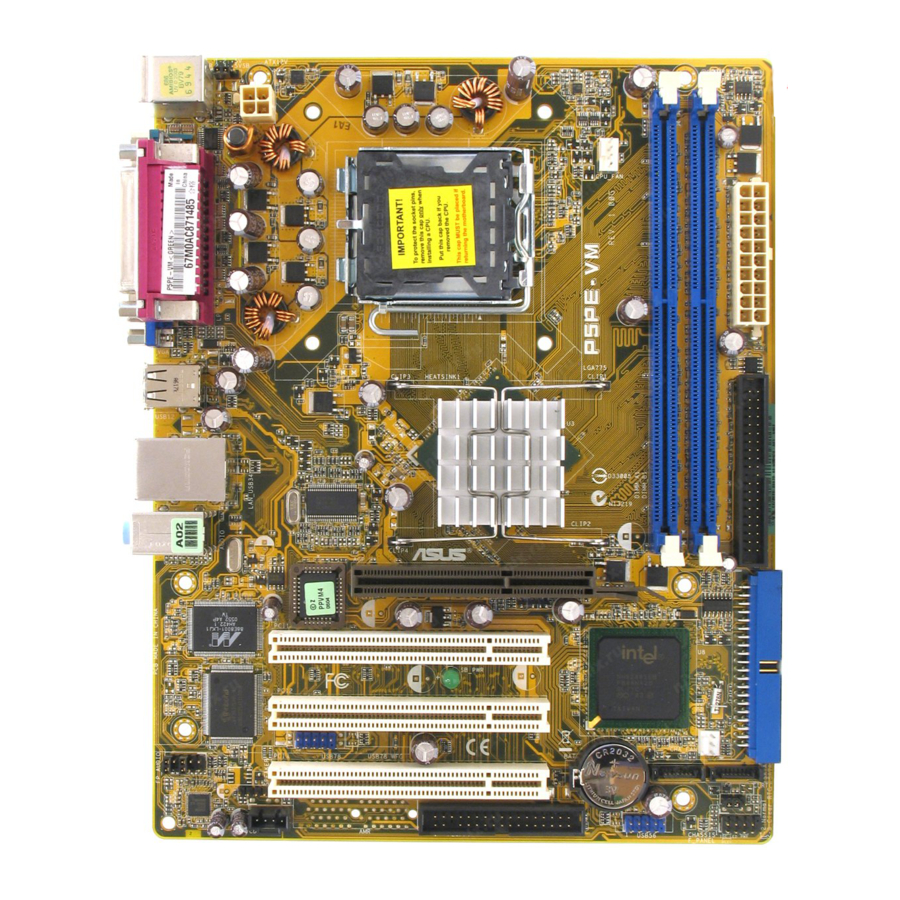
Page 19: Motherboard Layout
Bottom : Top: USB3 RJ-45 USB4 Top:Line In Center:Line Out Below:Mic In BIOS Marvell 88E8001 USB78 SPEAKER FP_AUDIO AD1888 ASUS P5PE-VM 19.3cm (7.6in) LGA775 Intel 865G PCI1 SB_PWR PCI2 CR2032 3V PCI3 Lithium Cell CMOS Power FLOPPY Intel ICH5 SATA1... -
Page 20: Central Processing Unit (Cpu)
Contact your retailer immediately if the PnP cap is missing, or if you see any damage to the PnP cap/socket pins/motherboard components. ASUS will shoulder the cost of repair only if the damage is shipment/ transit-related. •... - Page 21 The socket alignment key should fit into the CPU notch. ASUS P5PE-VM This side of the cam box should face you. Load plate Alignment key Gold triangle mark...
- Page 22 Close the load plate (A), then push the load lever (B) until it snaps into the retention tab. The CPU fits in only one correct orientation. DO NOT force the CPU into the socket to prevent bending the connectors on the socket and damaging the CPU! Notes on Intel •...
-
Page 23: Installing The Cpu Heatsink And Fan
CPU fan cable is closest to the CPU fan connector. Make sure to orient each fastener with the narrow end of the groove pointing outward. (The photo shows the groove shaded for emphasis.) ASUS P5PE-VM Pentium ® ® Pentium 4 LGA775 heatsink and fan assembly comes in ®... - Page 24 Connect the CPU fan cable to the connector on the motherboard labeled CPU_FAN. P5PE-VM CPU Fan Connector Do not forget to connect the CPU fan connector! Hardware monitoring errors can occur if you fail to plug this connector. 1-12...
-
Page 25: Uninstalling The Cpu Heatsink And Fan
To uninstall the CPU heatsink and fan: Disconnect the CPU fan cable from the connector on the motherboard. Rotate each fastener counterclockwise. Pull up two fasteners at a time in a diagonal sequence to disengage the heatsink and fan assembly from the motherboard. ASUS P5PE-VM 1-13... - Page 26 Carefully remove the heatsink and fan assembly from the motherboard. Rotate each fastener clockwise to ensure correct orientation when reinstalling. The narrow end of the groove should point outward after resetting. (The photo shows the groove shaded for emphasis.) 1-14 Narrow end of the groove Chapter 1: Product introduction...
-
Page 27: Memory Configurations
1.7.1 Overview The motherboard comes with four 184-pin Double Data Rate (DDR) Dual Inline Memory Modules (DIMM) sockets. The following figure illustrates the location of the sockets: P5PE-VM 184-pin DDR DIMM Sockets Channel Channel A Channel B 1.7.2 Memory configurations You may install 64MB,128 MB, 256 MB, 512 MB, and 1 GB DDR DIMMs into the DIMM sockets using the memory configuration in this section. -
Page 28: Ddr Qualified Vendors List
DDR Qualified Vendors List The following table lists the memory modules that have been tested and qualified for use with this motherboard. Visit the ASUS website (www.asus. com) for the latest DDR DIMM modules for this motherboard. DDR 400 Qualified Vendors List... -
Page 29: Installing A Dimm
Support the DIMM lightly with your fingers when pressing the retaining clips. The DIMM might get damaged when it flips out with extra force. Remove the DIMM from the socket. ASUS P5PE-VM DDR DIMM notch Unlocked retaining clip Locked Retaining Clip... -
Page 30: Expansion Slots
Expansion slots In the future, you may need to install expansion cards. The following sub-sections describe the slots and the expansion cards that they support. Make sure to unplug the power cord before adding or removing expansion cards. Failure to do so may cause you physical injury and damage motherboard components. -
Page 31: Standard Interrupt Assignments
When using PCI cards on shared slots, ensure that the drivers support “Share IRQ” or that the cards do not need IRQ assignments. Otherwise, conflicts will arise between the two PCI groups, making the system unstable and the card inoperable. ASUS P5PE-VM Standard Function System Timer Keyboard Controller... -
Page 32: Pci Slots
AGP slot on your mother board. Install only 1.5V or 0.8V AGP cards on this motherboard! This motherboard does not support 3.3V AGP cards. P5PE-VM Accelerated Graphics Port (AGP) 1-20 Keyed for 1.5v Chapter 1: Product introduction... -
Page 33: Clear Rtc Ram
Except when clearing the RTC RAM, never remove the cap on CLRTC jumper default position. Removing the cap will cause system boot failure! P5PE-VM Clear RTC RAM You do not need to clear the RTC when the system hangs due to overclocking. -
Page 34: Keyboard Power (3-Pin Kbpwr)
(the default is the Space Bar). This feature requires an ATX power supply that can supply at least 1A on the +5VSB lead, and a corresponding setting in the BIOS. KBPWR +5VSB (Default) P5PE-VM Keyboard Power Setting 1-22 Chapter 1: Product introduction... -
Page 35: 1.10 Connectors
In 4-channel and 6-channel configuration, the function of this port becomes Front Speaker Out. Microphone port (pink). This port connects a microphone. In a 6-channel configuration, the function of this port becomes Rear Speaker Out. ASUS P5PE-VM SPEED LED Status Description 10 Mbps connection... -
Page 36: 1.10.2 Internal Connectors
Pin 5 on the connector is removed to prevent incorrect cable connection when using an FDD cable with a covered Pin 5. P5PE-VM Floppy Disk Drive Connector 1-24 Headset... - Page 37 • Use the 80-conductor IDE cable for Ultra DMA devices. If any device jumper is set to “Cable-select”, make sure all other device jumpers have the same setting. P5PE-VM IDE Connectors ASUS P5PE-VM Mode of Devices Cable Connector Black Master...
- Page 38 Serial ATA connectors (7-pin SATA1, SATA2) These connectors are for the Serial ATA signal cables for Serial ATA hard disk drives. P5PE-VM SATA Connectors Install the Windows Pack1 or later before using Serial ATA. CPU and Chassis fan connectors (4-pin CPU_FAN, 3-pin CHA_FAN) The fan connectors support cooling fans of 350mA~740mA (8.88W...
-
Page 39: Speaker Out Connector (4-Pin Speaker)
This connector is for a chassis-mounted front panel audio I/O module that supports legacy AC ‘97 audio standard. Connect one end of the front panel audio I/O module cable to this connector. P5PE-VM Front Panel Audio Connector ASUS P5PE-VM SPEAKER... - Page 40 Use of a PSU with a higher power output is recommended when configuring a system with more power-consuming devices. The system may become unstable or may not boot up if the power is inadequate. P5PE-VM ATX Power Connector 1-28 ATX12V +12VDC +12VDC +12.0Volts...
-
Page 41: Usb Connectors (10-1 Pin Usb56, Usb78)
These USB connectors comply with USB 2.0 specification that supports up to 480 Mbps connection speed. P5PE-VM USB 2.0 Connectors Never connect a 1394 cable to the USB connectors. Doing so will damage the motherboard! The USB/GAME module is purchased separately. -
Page 42: System Panel Connector
10. System panel connector (10-1 pin PANEL) This connector supports several chassis-mounted functions. P5PE-VM System Panel Connector The sytem panel connector is color-coded for easy connection. Refer to the connector description below for details. • System power LED (2-pin PLED) This 2-pin connector is for the system power LED. -
Page 43: Chapter 2: Bios Setup
This chapter tells how to change the system settings through the BIOS Setup menus. Detailed descriptions of the BIOS parameters are also provided. BIOS setup ASUS P5PE-VM... -
Page 44: Managing And Updating Your Bios
The following utilities allow you to manage and update the motherboard Basic Input/Output System (BIOS) setup. ASUS AFUDOS (Updates the BIOS in DOS mode using a bootable floppy disk.) ASUS EZ Flash (Updates the BIOS using a floppy disk during POST.) -
Page 45: Asus Ez Flash Utility
2.1.2 ASUS EZ Flash utility The ASUS EZ Flash feature allows you to update the BIOS without having to go through the long process of booting from a floppy disk and using a DOS-based utility. The EZ Flash utility is built-in the BIOS chip so it is accessible by pressing <Alt>... -
Page 46: Afudos Utility
2.1.3 AFUDOS utility The AFUDOS utility allows you to update the BIOS file in DOS environment using a bootable floppy disk with the updated BIOS file. This utility also allows you to copy the current BIOS file that you can use as backup when the BIOS fails or gets corrupted during the updating process. -
Page 47: Updating The Bios File
Updating the BIOS file To update the BIOS file using the AFUDOS utility: Visit the ASUS website (www.asus.com) and download the latest BIOS file for the motherboard. Save the BIOS file to a bootable floppy disk. Write the BIOS filename on a piece of paper. You need to type the exact BIOS filename at the DOS prompt. -
Page 48: Asus Update Utility
2.1.4 ASUS Update utility The ASUS Update is a utility that allows you to manage, save, and update the motherboard BIOS in Windows allows you to: • Save the current BIOS file • Download the latest BIOS file from the Internet •... -
Page 49: Updating The Bios Through The Internet
Updating the BIOS through the Internet To update the BIOS through the Internet: Launch the ASUS Update utility from the Windows Start > Programs > ASUS > ASUSUpdate > ASUSUpdate. The ASUS Update main window appears. Select Update BIOS from... -
Page 50: Updating The Bios Through A Bios File
Updating the BIOS through a BIOS file To update the BIOS through a BIOS file: Launch the ASUS Update utility from the Windows clicking Start > Programs > ASUS > ASUSUpdate > ASUSUpdate. The ASUS Update main window appears. Select Update BIOS from a file option from the drop-down menu, then click Next. -
Page 51: Bios Setup Program
The BIOS setup screens shown in this section are for reference purposes only, and may not exactly match what you see on your screen. • Visit the ASUS website (www.asus.com) to download the latest BIOS file for this motherboard. ASUS P5PE-VM... -
Page 52: Bios Menu Screen
2.2.1 BIOS menu screen Menu items Menu bar System Time System Date Legacy Diskette A Primary IDE Master Primary IDE Slave Secondary IDE Master Secondary IDE Slave Third IDE Master Fourth IDE Master IDE Configuration System Information Sub-menu items 2.2.2 Menu bar The menu bar on top of the screen has the following main items: Main... -
Page 53: Menu Items
/<Page Down> keys to display the other items on the screen. 2.2.9 General help At the top right corner of the menu screen is a brief description of the selected item. ASUS P5PE-VM System Time [11:10:19] Use [ENTER], [TAB] System Date [Thu 03/27/2003] or [SHIFT-TAB] to Legacy Diskette A [1.44M, 3.5 in]... -
Page 54: Main Menu
Main menu When you enter the BIOS Setup program, the Main menu screen appears, giving you an overview of the basic system information. Refer to section “2.2.1 BIOS menu screen” for information on the menu screen items and how to navigate through them. System Time System Date Legacy Diskette A... -
Page 55: Fourth Ide Master
When set to [Disabled], the data transfer from and to the device occurs one sector at a time. Configuration options: [Disabled] [Auto] ASUS P5PE-VM [Auto] [Auto] [Auto]... -
Page 56: Ide Configuration
PIO Mode [Auto] Selects the PIO mode. Configuration options: [Auto] [0] [1] [2] [3] [4] DMA Mode [Auto] Selects the DMA mode. Configuration options: [Auto] [SWDMA0] [SWDMA1] [SWDMA2] [MWDMA0] [MWDMA1] [MWDMA2] [UDMA0] [UDMA1] [UDMA2] [UDMA3] [UDMA4] [UDMA5] SMART Monitoring [Auto] Sets the Smart Monitoring, Analysis, and Reporting Technology. -
Page 57: System Information
: Intel(R) Pentium(R) 4 CPU 2.66GHz Speed : 2666MHz Count System Memory Installed Size: 256MB Usable Size: 256MB AMI BIOS Displays the auto-detected BIOS information Processor Displays the auto-detected CPU specification System Memory Displays the auto-detected system memory ASUS P5PE-VM 2-15... -
Page 58: Advanced Menu
Advanced menu The Advanced menu items allow you to change the settings for the CPU and other system devices. Take caution when changing the settings of the Advanced menu items. Incorrect field values can cause the system to malfunction. CPU Configuration Chipset Onboard Devices Configuration PCIPnP... - Page 59 [Automatic], you can adjust the system power settings in the operating system to use the EIST feature. Set this item to [Disabled] if you do not want to use the EIST. Configuration options: [Automatic] [Disabled] ASUS P5PE-VM Technology (EIST). ®...
-
Page 60: Chipset
2.4.2 Chipset The Chipset menu allows you to change the advanced chipset settings. Select an item then press <Enter> to display the sub-menu. Advanced Chipset Settings WARNING: Setting wrong values in below sections may cause the system to malfunction. Configure DRAM Timing by SPD Performance Acceleration Mode DRAM Idle Timer DRAM Refresh Rate... - Page 61 Graphics Aperture Size [ 64MB] Allows you to set the size of mapped memory for the AGP graphic data. Configuration options: [16MB] [32MB] [64MB] [128MB] [256MB] MPS Revision [1.4] Sets the MPS revision version. Configuration options: [1.1] [1.4] ASUS P5PE-VM 2-19...
-
Page 62: Onboard Devices Configuration
2.4.3 Onboard Devices Configuration Onboard AC’97 Audio Onboard LAN Onboard LAN Boot ROM Serial Port1 Address Parallel Port Address Parallel Port Mode ECP Mode DMA Channel Parallel Port IRQ Onboard AC’97 Audio [Auto] When set to Auto, the BIOS detects whether you are using any audio device. -
Page 63: Pci Pnp
Palette Snooping [Disabled] When set to [Enabled], the pallete snooping feature informs the PCI devices that an ISA graphics device is installed in the system so that the latter can function correctly. Configuration options: [Disabled] [Enabled] ASUS P5PE-VM [No] [64] [Yes]... -
Page 64: Usb Configuration
IRQ-xx assigned to [PCI Device] When set to [PCI Device], the specific IRQ is free for use of PCI/PnP devices. When set to [Reserved], the IRQ is reserved for legacy ISA devices. Configuration options: [PCI Device] [Reserved] 2.4.5 USB Configuration The items in this menu allows you to change the USB-related features. -
Page 65: Usb Mass Storage Device Configuration
Forced FDD option can be used to force an HDD formatted drive to boot as FDD (for example, ZIP drive). The Emulation Type items appear only when there are installed USB devices. ASUS P5PE-VM [20 Sec] 2-23... -
Page 66: Power Menu
Power menu The Power menu items allow you to change the settings for the Advanced Power Management (APM). Select an item then press <Enter> to display the configuration options. Suspend Mode ACPI 2.0 Support ACPI APIC Support APM Configuration Hardware Monitor 2.5.1 Suspend Mode [Auto] Allows you to select the Advanced Configuration and Power Interface... -
Page 67: Apm Configuration
Thus, connection cannot be made on the first try. Turning an external modem off and then back on while the computer is off causes an initialization string that turns the system power on. ASUS P5PE-VM [On/Off] [Power Off] [Disabled]... -
Page 68: Hardware Monitor
Power On By PCI Devices [Enabled] When set to [Enabled], this parameter allows you to turn on the system through a PCI LAN or modem card. This feature requires an ATX power supply that provides at least 1A on the +5VSB lead. Configuration options: [Disabled] [Enabled] Power On By PS/2 Keyboard [Ctrl-Esc] Allows you to use specific keys on the keyboard to turn on the system. -
Page 69: Chassis Fan Speed [Xxxxrpm] Or [N/A]
(RPM). If the fan is not connected to the chassis, the specific field shows N/A. VCORE Voltage, 3.3V Voltage, 5V Voltage, 12V Voltage The onboard hardware monitor automatically detects the voltage output through the onboard voltage regulators. ASUS P5PE-VM 2-27... -
Page 70: Boot Menu
Configuration options: [xxxxx Drive] [Disabled] 2-28 Enter Go to Sub-screen [1st FLOPPY DRIVE] [PM-ST330620A] [PS-ASUS CD-S360] Enter Go to Sub-screen Chapter 2: BIOS setup Select Screen Select Item General Help Save and Exit... -
Page 71: Boot Settings Configuration
This allows you to enable or disable the full screen logo display feature. Configuration options: [Disabled] [Enabled] Set this item to [Enabled] to use the ASUS MyLogo™ feature. Add On ROM Display Mode [Force BIOS] Sets the display mode for option ROM. -
Page 72: Interrupt 19 Capture [Disabled]
Interrupt 19 Capture [Disabled] When set to [Enabled], this function allows the option ROMs to trap Interrupt 19. Configuration options: [Disabled] [Enabled] 2.6.3 Security The Security menu items allow you to change the system security settings. Select an item then press <Enter> to display the configuration options. Security Settings Supervisor Password User Password... -
Page 73: Change User Password
When set to [Setup], BIOS checks for user password when accessing the Setup utility. When set to [Always], BIOS checks for user password both when accessing Setup and booting the system. Configuration options: [Setup] [Always] ASUS P5PE-VM [Full Access] [Setup] Select Screen... -
Page 74: Exit Menu
Exit menu The Exit menu items allow you to load the optimal or failsafe default values for the BIOS items, and save or discard your changes to the BIOS items. Exit Options Exit & Save Changes Exit & Discard Changes Discard Changes Load Setup Defaults Pressing <Esc>... -
Page 75: Chapter 3: Software Support
This chapter describes the contents of the support CD that comes with the motherboard package. Software support ASUS P5PE-VM... -
Page 76: Installing An Operating System
The contents of the support CD are subject to change at any time without notice. Visit the ASUS website(www.asus.com) for updates. 3.2.1 Running the support CD Place the support CD to the optical drive. -
Page 77: Drivers Menu
Onboard VGA driver. ® SoundMAX Audio Driver and Application Installs the SoundMax Audio driver and application. Marvell Yukon Gigabit Ethernet Driver Installs the Marvell Yukon Gigabit Ethernet driver. ® USB2.0 Driver Installs the Universal Serial Bus (USB2.0) driver. ASUS P5PE-VM... -
Page 78: Utilities Menu
This utility helps you keep your computer in healthy operating condition. ASUS Update The ASUS Update utility allows you to update the motherboard BIOS in a Windows environment. This utility requires an Internet connection either ®... -
Page 79: Asus Contact Information
3.2.4 ASUS Contact information Click the Contact tab to display the ASUS contact information. You can also find this information on the inside front cover of this user guide. ASUS P5PE-VM... - Page 80 Chapter 3: Software support...
Need help?
Do you have a question about the P5PE-VM and is the answer not in the manual?
Questions and answers