Table of Contents
Advertisement
Advertisement
Table of Contents

Related Manuals for Asus P5P800 SE


Summary of Contents for Asus P5P800 SE
- Page 1 P5P800 SE...
- Page 2 Product warranty or service will not be extended if: (1) the product is repaired, modified or altered, unless such repair, modification of alteration is authorized in writing by ASUS; or (2) the serial number of the product is defaced or missing.
-
Page 3: Table Of Contents
Welcome! ................1-1 Package contents ..............1-1 Special features ..............1-2 1.3.1 Product highlights ........... 1-2 1.3.2 Innovative ASUS features ........1-4 Chapter 2: Hardware information Chapter 2: Hardware information Chapter 2: Hardware information Chapter 2: Hardware information Chapter 2: Hardware information Before you proceed .............. - Page 4 Creating a bootable floppy disk ......4-1 4.1.2 ASUS EZ Flash utility ..........4-2 4.1.3 AFUDOS utility ............4-3 4.1.4 ASUS CrashFree BIOS 2 utility ........ 4-5 4.1.5 ASUS Update utility ..........4-7 BIOS setup program ............4-10 4.2.1 BIOS menu screen ..........4-11 4.2.2...
- Page 5 5.2.2 Drivers menu ............5-2 5.2.3 Utilities menu ............5-3 5.2.4 Manuals menu ............5-4 5.2.5 ASUS Contact information ........5-4 5.2.6 Other information ........... 5-5 Software information ............5-7 ASUS MyLogo™ ..............5-7 Appendix: CPU features Appendix: CPU features...
- Page 6 Contents Enhanced Intel SpeedStep ® Technology (EIST) ....A-1 A.2.1 System requirements ..........A-1 A.2.2 Using the EIST ............A-2 Intel ® Hyper-Threading Technology ........A-3 Using the Hyper-Threading Technology ....... A-3 v i v i v i v i v i...
-
Page 7: Notices
Notices Federal Communications Commission Statement Federal Communications Commission Statement Federal Communications Commission Statement Federal Communications Commission Statement Federal Communications Commission Statement This device complies with Part 15 of the FCC Rules. Operation is subject to the following two conditions: • This device may not cause harmful interference, and •... -
Page 8: Safety Information
Safety information Electrical safety Electrical safety Electrical safety Electrical safety Electrical safety • To prevent electrical shock hazard, disconnect the power cable from the electrical outlet before relocating the system. • When adding or removing devices to or from the system, ensure that the power cables for the devices are unplugged before the signal cables are connected. -
Page 9: About This Guide
A S U S w e b s i t e s A S U S w e b s i t e s The ASUS website provides updated information on ASUS hardware and software products. Refer to the ASUS contact information. -
Page 10: Typography
Conventions used in this guide Conventions used in this guide Conventions used in this guide Conventions used in this guide Conventions used in this guide To make sure that you perform certain tasks properly, take note of the following symbols used throughout this manual. D A N G E R / W A R N I N G : D A N G E R / W A R N I N G : D A N G E R / W A R N I N G : Information to prevent injury to yourself... -
Page 11: P5P800 Se Specifications Summary
L A N L A N L A N ASUS AI Overclocking (Intelligent CPU frequency tuner) O v e r c l o c k i n g O v e r c l o c k i n g... - Page 12 ASUS PC Probe ASUS Live Update Utility Anti-virus software (OEM version) *Specifications are subject to change without notice. x i i...
- Page 13 This chapter describes the motherboard features and the new technologies it supports. Product introduction...
- Page 14 Chapter summary Welcome! ................1-1 Package contents ..............1-1 Special features ..............1-2 A S U S P 5 P 8 0 0 S E A S U S P 5 P 8 0 0 S E A S U S P 5 P 8 0 0 S E A S U S P 5 P 8 0 0 S E A S U S P 5 P 8 0 0 S E...
-
Page 15: Welcome
P 5 P 8 0 0 S E m o t h e r b o a r d ! The motherboard delivers a host of new features and latest technologies, making it another standout in the long line of ASUS quality motherboards! Before you start installing the motherboard, and hardware devices on it, check the items in your package with the list below. -
Page 16: Special Features
ASUS Hyper-Path Technology ASUS Hyper-Path Technology ASUS Hyper-Path Technology ASUS Hyper-Path Technology This unique technology from ASUS optimizes the true potential of the Intel ® 865PE chipset to deliver the highest performance among competing 865PE-based solutions. Dual-channel DDR400 memory support... - Page 17 6-channel audio support 6-channel audio support 6-channel audio support 6-channel audio support 6-channel audio support The motherboard comes with the ADI AD1888 SoundMAX audio CODEC that lets you enjoy high-quality 6-channel audio without having to buy advanced sound cards. The ADI SoundMAX Digital Audio System features state-of-the-art DLS2 MIDI synthesizer with Yamaha DLS by XG sound set, 5.1 Virtual Theater™...
-
Page 18: Innovative Asus Features
ASUS Q-Fan technology ASUS Q-Fan technology ASUS Q-Fan technology ASUS Q-Fan technology The ASUS Q-Fan technology smartly adjusts the CPU fan speed according to the system loading to ensure quiet, cool, and efficient operation. See page 4-32 for details. ASUS MyLogo™... - Page 19 This chapter lists the hardware setup procedures that you have to perform when installing system components. It includes description of the jumpers and connectors on the motherboard. Hardware information...
- Page 20 Chapter summary Before you proceed .............. 2-1 Motherboard overview ............2-2 Central Processing Unit (CPU) ..........2-6 System memory ..............2-13 Expansion slots ..............2-17 Jumpers ................2-20 Connectors ................. 2-23 A S U S P 5 P 8 0 0 S E A S U S P 5 P 8 0 0 S E A S U S P 5 P 8 0 0 S E A S U S P 5 P 8 0 0 S E...
-
Page 21: Before You Proceed
Before you proceed Take note of the following precautions before you install motherboard components or change any motherboard settings. • Unplug the power cord from the wall socket before touching any component. • Use a grounded wrist strap or touch a safely grounded object or to a metal object, such as the power supply case, before handling components to avoid damaging them due to static electricity •... -
Page 22: Motherboard Overview
Motherboard overview Before you install the motherboard, study the configuration of your chassis to ensure that the motherboard fits into it. Make sure to unplug the power cord before installing or removing the motherboard. Failure to do so can cause you physical injury and damage motherboard components. -
Page 23: Motherboard Layout
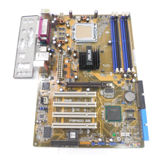
2.2.3 2.2.3 Motherboard layout Motherboard layout 2.2.3 2.2.3 2.2.3 Motherboard layout Motherboard layout Motherboard layout 21.3cm (8.4in) PS/2KBMS KBPWR T: Mouse B: Keyboard ATX12V LGA775 SPDIF_O COM1 USB20_12 CPU_FAN Intel 82865PE USB2.0 Top: Memory T: USB4 RJ-45 Controller B: USB3 Top:Line In Center:Line Out Below:Mic In... -
Page 24: Layout Contents
2.2.4 2.2.4 Layout Contents Layout Contents 2.2.4 2.2.4 2.2.4 Layout Contents Layout Contents Layout Contents S l o t s S l o t s S l o t s P a g e P a g e P a g e S l o t s S l o t s P a g e... - Page 25 I n t e r n a l c o n n e c t o r s I n t e r n a l c o n n e c t o r s I n t e r n a l c o n n e c t o r s I n t e r n a l c o n n e c t o r s I n t e r n a l c o n n e c t o r s P a g e...
-
Page 26: Central Processing Unit (Cpu)
Contact your retailer immediately if the PnP cap is missing, or if you see any damage to the PnP cap/socket pins/motherboard components. ASUS will shoulder the cost of repair only if the damage is shipment/ transit-related. •... - Page 27 Press the load lever with your thumb (A) and move it to the left (B) until it is released from the retention tab. P n P C a p P n P C a p P n P C a p P n P C a p P n P C a p R e t e n t i o n t a b...
- Page 28 Close the load plate (A), then push the load lever (B) until it snaps into the retention tab. The CPU fits in only one correct orientation. DO NOT force the CPU into the socket to prevent bending the connectors on the socket and damaging the CPU! The motherboard supports Intel ®...
-
Page 29: Installling The Cpu Heatsink And Fan
2.3.2 2.3.2 2.3.2 Installling the CPU heatsink and fan Installling the CPU heatsink and fan Installling the CPU heatsink and fan 2.3.2 2.3.2 Installling the CPU heatsink and fan Installling the CPU heatsink and fan The Intel ® Pentium ® 4/Intel ®... - Page 30 Push down two fasteners at a time in a diagonal sequence to secure the heatsink and fan assembly in place. When the fan and heatsink assembly is in place, connect the CPU fan cable to the connector on the motherboard labeled CPU_FAN. CPU_FAN CPU FAN PWR CPU FAN IN...
-
Page 31: Uninstalling The Cpu Heatsink And Fan
2.3.3 2.3.3 2.3.3 2.3.3 2.3.3 Uninstalling the CPU heatsink and fan Uninstalling the CPU heatsink and fan Uninstalling the CPU heatsink and fan Uninstalling the CPU heatsink and fan Uninstalling the CPU heatsink and fan To uninstall the CPU heatsink and fan: Disconnect the CPU fan cable from the connector on the motherboard. - Page 32 Remove the heatsink and fan assembly from the motherboard. Rotate each fastener clockwise to reset the orientation. When reset, each fastener should be oriented as shown, with the narrow groove directed outward. 2 - 1 2 2 - 1 2 2 - 1 2 C h a p t e r 2 : H a r d w a r e i n f o r m a t i o n C h a p t e r 2 : H a r d w a r e i n f o r m a t i o n...
-
Page 33: System Memory
System memory 2.4.1 2.4.1 2.4.1 Overview Overview Overview 2.4.1 2.4.1 Overview Overview The motherboard comes with four Double Data Rate (DDR) Dual Inline Memory Modules (DIMM) sockets. The following figure illustrates the location of the sockets: ® P5P800 SE P5P800 SE 184-pin DDR DIMM sockets •... - Page 34 333/266 MHz *When using 800 MHz FSB CPU, PC2700 DDR DIMMs run only at 320MHz (not 333MHz) due to chipset limitation. Visit the ASUS website (www.asus.com) for the latest DDR 400 Qualified Vendors List. 2 - 1 4 2 - 1 4...
- Page 35 DDR 400 Qualified Vendors List DDR 400 Qualified Vendors List DDR 400 Qualified Vendors List DDR 400 Qualified Vendors List DDR 400 Qualified Vendors List DIMM support S i z e S i z e S i z e S i z e S i z e V e n d o r V e n d o r...
-
Page 36: Installing A Dimm
2.4.3 2.4.3 Installing a DIMM Installing a DIMM 2.4.3 2.4.3 2.4.3 Installing a DIMM Installing a DIMM Installing a DIMM Make sure to unplug the power supply before adding or removing DIMMs or other system components. Failure to do so may cause severe damage to both the motherboard and the components. -
Page 37: Expansion Slots
Expansion slots In the future, you may need to install expansion cards. The following sub-sections describe the slots and the expansion cards that they support. Make sure to unplug the power cord before adding or removing expansion cards. Failure to do so may cause you physical injury and damage motherboard components. -
Page 38: Interrupt Assignments
2.5.3 2.5.3 2.5.3 Interrupt assignments Interrupt assignments Interrupt assignments 2.5.3 2.5.3 Interrupt assignments Interrupt assignments Standard interrupt assignments Standard interrupt assignments Standard interrupt assignments Standard interrupt assignments Standard interrupt assignments I R Q I R Q I R Q I R Q I R Q P r i o r i t y P r i o r i t y... -
Page 39: Pci Slots
2.5.4 2.5.4 PCI slots PCI slots 2.5.4 2.5.4 2.5.4 PCI slots PCI slots PCI slots The PCI slots support cards such as a LAN card, SCSI card, USB card, and other cards that comply with PCI specifications. The figure shows a LAN card installed on a PCI slot. -
Page 40: Jumpers
Jumpers 1 . 1 . C l e a r R T C R A M ( C L R T C ) C l e a r R T C R A M ( C L R T C ) C l e a r R T C R A M ( C L R T C ) C l e a r R T C R A M ( C L R T C ) C l e a r R T C R A M ( C L R T C ) - Page 41 2 . 2 . U S B d e v i c e w a k e - u p ( 3 - p i n U S B P W 1 2 , U S B P W 3 4 , U S B d e v i c e w a k e - u p ( 3 - p i n U S B P W 1 2 , U S B P W 3 4 , U S B d e v i c e w a k e - u p ( 3 - p i n U S B P W 1 2 , U S B P W 3 4 , U S B d e v i c e w a k e - u p ( 3 - p i n U S B P W 1 2 , U S B P W 3 4 ,...
- Page 42 3 . 3 . K e y b o a r d p o w e r ( 3 - p i n K B P W R ) K e y b o a r d p o w e r ( 3 - p i n K B P W R ) K e y b o a r d p o w e r ( 3 - p i n K B P W R ) K e y b o a r d p o w e r ( 3 - p i n K B P W R ) K e y b o a r d p o w e r ( 3 - p i n K B P W R )
-
Page 43: Connectors
Connectors 2.7.1 2.7.1 2.7.1 Rear panel connectors Rear panel connectors Rear panel connectors 2.7.1 2.7.1 Rear panel connectors Rear panel connectors 1 . 1 . P S / 2 m o u s e p o r t ( g r e e n ) . P S / 2 m o u s e p o r t ( g r e e n ) . - Page 44 2, 4, or 6-channel audio configuration 2, 4, or 6-channel audio configuration 2, 4, or 6-channel audio configuration 2, 4, or 6-channel audio configuration 2, 4, or 6-channel audio configuration P o r t P o r t P o r t P o r t P o r t H e a d s e t...
-
Page 45: Internal Connectors
2.7.2 2.7.2 Internal connectors Internal connectors 2.7.2 2.7.2 2.7.2 Internal connectors Internal connectors Internal connectors 1 . 1 . F l o p p y d i s k d r i v e c o n n e c t o r ( 3 4 - 1 p i n F L O P P Y ) F l o p p y d i s k d r i v e c o n n e c t o r ( 3 4 - 1 p i n F L O P P Y ) F l o p p y d i s k d r i v e c o n n e c t o r ( 3 4 - 1 p i n F L O P P Y ) F l o p p y d i s k d r i v e c o n n e c t o r ( 3 4 - 1 p i n F L O P P Y ) - Page 46 3 . 3 . S e r i a l A T A c o n n e c t o r s ( 7 - p i n S A T A 1 , S A T A 2 ) S e r i a l A T A c o n n e c t o r s ( 7 - p i n S A T A 1 , S A T A 2 ) S e r i a l A T A c o n n e c t o r s ( 7 - p i n S A T A 1 , S A T A 2 ) S e r i a l A T A c o n n e c t o r s ( 7 - p i n S A T A 1 , S A T A 2 )
- Page 47 P a r a l l e l A T A a n d S e r i a l A T A d e v i c e c o n f i g u r a t i o n s P a r a l l e l A T A a n d S e r i a l A T A d e v i c e c o n f i g u r a t i o n s P a r a l l e l A T A a n d S e r i a l A T A d e v i c e c o n f i g u r a t i o n s P a r a l l e l A T A a n d S e r i a l A T A d e v i c e c o n f i g u r a t i o n s...
- Page 48 4 . 4 . C P U a n d C h a s s i s f a n c o n n e c t o r s C P U a n d C h a s s i s f a n c o n n e c t o r s C P U a n d C h a s s i s f a n c o n n e c t o r s C P U a n d C h a s s i s f a n c o n n e c t o r s C P U a n d C h a s s i s f a n c o n n e c t o r s...
- Page 49 6 . 6 . U S B c o n n e c t o r s ( 1 0 - 1 p i n U S B 5 6 , U S B 7 8 ) U S B c o n n e c t o r s ( 1 0 - 1 p i n U S B 5 6 , U S B 7 8 ) U S B c o n n e c t o r s ( 1 0 - 1 p i n U S B 5 6 , U S B 7 8 ) U S B c o n n e c t o r s ( 1 0 - 1 p i n U S B 5 6 , U S B 7 8 ) U S B c o n n e c t o r s ( 1 0 - 1 p i n U S B 5 6 , U S B 7 8 )
- Page 50 7 . 7 . A T X p o w e r c o n n e c t o r s ( 2 4 - p i n E A T X P W R , A T X p o w e r c o n n e c t o r s ( 2 4 - p i n E A T X P W R , A T X p o w e r c o n n e c t o r s ( 2 4 - p i n E A T X P W R , A T X p o w e r c o n n e c t o r s ( 2 4 - p i n E A T X P W R , A T X p o w e r c o n n e c t o r s ( 2 4 - p i n E A T X P W R ,...
- Page 51 8 . 8 . I n t e r n a l a u d i o c o n n e c t o r ( 4 - p i n C D , A U X ) I n t e r n a l a u d i o c o n n e c t o r ( 4 - p i n C D , A U X ) I n t e r n a l a u d i o c o n n e c t o r ( 4 - p i n C D , A U X ) I n t e r n a l a u d i o c o n n e c t o r ( 4 - p i n C D , A U X ) I n t e r n a l a u d i o c o n n e c t o r ( 4 - p i n C D , A U X )
- Page 52 1 0 . 1 0 . 1 0 . 1 0 . 1 0 . C h a s s i s i n t r u s i o n c o n n e c t o r ( 4 - 1 p i n C H A S S I S ) C h a s s i s i n t r u s i o n c o n n e c t o r ( 4 - 1 p i n C H A S S I S ) C h a s s i s i n t r u s i o n c o n n e c t o r ( 4 - 1 p i n C H A S S I S ) C h a s s i s i n t r u s i o n c o n n e c t o r ( 4 - 1 p i n C H A S S I S )
-
Page 53: System Panel Connector
1 2 . 1 2 . 1 2 . S y s t e m p a n e l c o n n e c t o r ( 2 0 - 1 p i n P A N E L ) 1 2 . - Page 54 2 - 3 4 2 - 3 4 2 - 3 4 C h a p t e r 2 : H a r d w a r e i n f o r m a t i o n C h a p t e r 2 : H a r d w a r e i n f o r m a t i o n C h a p t e r 2 : H a r d w a r e i n f o r m a t i o n 2 - 3 4...
- Page 55 This chapter describes the power up sequence, the vocal POST messages, and ways of shutting down the system. Powering up...
- Page 56 Chapter summary Starting up for the first time ..........3-1 Powering off the computer ..........3-2 A S U S P 5 P 8 0 0 S E A S U S P 5 P 8 0 0 S E A S U S P 5 P 8 0 0 S E A S U S P 5 P 8 0 0 S E A S U S P 5 P 8 0 0 S E...
-
Page 57: Starting Up For The First Time
Starting up for the first time After making all the connections, replace the system case cover. Be sure that all switches are off. Connect the power cord to the power connector at the back of the system chassis. Connect the power cord to a power outlet that is equipped with a surge protector. -
Page 58: Powering Off The Computer
Powering off the computer 3.2.1 3.2.1 3.2.1 Using the OS shut down function Using the OS shut down function Using the OS shut down function 3.2.1 3.2.1 Using the OS shut down function Using the OS shut down function If you are using Windows ®... -
Page 59: Chapter 4: Bios Setup
This chapter tells how to change the system settings through the BIOS Setup menus. Detailed descriptions of the BIOS parameters are also provided. BIOS setup... - Page 60 Chapter summary Managing and updating your BIOS ........4-1 BIOS setup program ............4-10 Main menu ................4-13 Advanced menu ..............4-18 Power menu ................ 4-29 Boot menu ................4-34 Exit menu ................4-39 A S U S P 5 P 8 0 0 S E A S U S P 5 P 8 0 0 S E A S U S P 5 P 8 0 0 S E A S U S P 5 P 8 0 0 S E...
-
Page 61: Managing And Updating Your Bios
Refer to the corresponding sections for details on these utilities. Save a copy of the original motherboard BIOS file to a bootable floppy disk in case you need to restore the BIOS in the future. Copy the original motherboard BIOS using the ASUS Update or AFUDOS utilities. 4.1.1 4.1.1... -
Page 62: Asus Ez Flash Utility
ASUS EZ Flash utility ASUS EZ Flash utility The ASUS EZ Flash feature allows you to update the BIOS without having to go through the long process of booting from a floppy disk and using a DOS-based utility. The EZ Flash utility is built-in the BIOS chip so it is accessible by pressing <Alt>... -
Page 63: Afudos Utility
Press <Enter>. The utility copies the current BIOS file to the floppy disk. A:\>afudos /oOLDBIOS1.ROM AMI Firmware Update Utility - Version 1.19(ASUS V2.07(03.11.24BB)) Copyright (C) 2003 American Megatrends, Inc. All rights reserved. Reading flash ..done Write to file ...ok A:\>... - Page 64 Updating the BIOS file To update the BIOS file using the AFUDOS utility: Visit the ASUS website (www.asus.com) and download the latest BIOS file for the motherboard. Save the BIOS file to a bootable floppy disk. Write the BIOS filename on a piece of paper. You need to type the exact BIOS filename at the DOS prompt.
-
Page 65: Asus Crashfree Bios 2 Utility
ASUS CrashFree BIOS 2 utility ASUS CrashFree BIOS 2 utility The ASUS CrashFree BIOS 2 is an auto recovery tool that allows you to restore the BIOS file when it fails or gets corrupted during the updating process. You can update a corrupted BIOS file using the motherboard support CD or the floppy disk that contains the updated BIOS file. - Page 66 Restart the system after the utility completes the updating process. The recovered BIOS may not be the latest BIOS version for this motherboard. Visit the ASUS website (www.asus.com) to download the latest BIOS file. 4 - 6...
-
Page 67: Asus Update Utility
4.1.5 4.1.5 ASUS Update utility ASUS Update utility ASUS Update utility The ASUS Update is a utility that allows you to manage, save, and update the motherboard BIOS in Windows ® environment. The ASUS Update utility allows you to: • Save the current BIOS file •... - Page 68 Updating the BIOS through the Internet Updating the BIOS through the Internet Updating the BIOS through the Internet To update the BIOS through the Internet: Launch the ASUS Update utility from the Windows ® desktop by clicking S t a r t...
- Page 69 A S U S U p d a t e A S U S U p d a t e A S U S U p d a t e. The ASUS Update main window appears. A S U S U p d a t e...
-
Page 70: Bios Setup Program
The BIOS setup screens shown in this section are for reference purposes only, and may not exactly match what you see on your screen. • Visit the ASUS website (www.asus.com) to download the latest BIOS file for this motherboard and . 4 - 1 0 4 - 1 0... -
Page 71: Bios Menu Screen
Language [English] Use [+] or [-] to Primary IDE Master :[ST320413A] configure system time. Primary IDE Slave :[ASUS CD-S340] Secondary IDE Master :[Not Detected] Secondary IDE Slave :[Not Detected] Third IDE Master :[Not Detected] Fourth IDE Master... -
Page 72: Menu Items
M a i n M a i n shows the M a i n Primary IDE Master :[ST320413A] configure system time. Primary IDE Slave :[ASUS CD-S340] Secondary IDE Master :[Not Detected] Secondary IDE Slave :[Not Detected] Main menu items. Third IDE Master... -
Page 73: Main Menu
Main menu When you enter the BIOS Setup program, the Main menu screen appears, giving you an overview of the basic system information. Refer to section “4.2.1 BIOS menu screen” for information on the menu screen items and how to navigate through them. System Time [11:51:19] System Date... -
Page 74: Primary And Secondary Master/Slave; Third And Fourth Ide Master
4.3.5 4.3.5 Primary and Secondary Master/Slave; Primary and Secondary Master/Slave; 4.3.5 4.3.5 4.3.5 Primary and Secondary Master/Slave; Primary and Secondary Master/Slave; Primary and Secondary Master/Slave; Third and Fourth IDE Master Third and Fourth IDE Master Third and Fourth IDE Master Third and Fourth IDE Master Third and Fourth IDE Master While entering Setup, the BIOS automatically detects the presence of IDE... -
Page 75: Ide Configuration
PIO Mode [Auto] PIO Mode [Auto] PIO Mode [Auto] PIO Mode [Auto] PIO Mode [Auto] Selects the PIO mode. Configuration options: [Auto] [0] [1] [2] [3] [4] DMA Mode [Auto] DMA Mode [Auto] DMA Mode [Auto] DMA Mode [Auto] DMA Mode [Auto] Selects the DMA mode. - Page 76 Enhanced Mode Support On [S-ATA] The default setting S-ATA allows you to use native OS on Serial ATA and Parallel ATA ports. We recommend that you do not change the default setting for better OS compatibility. In this setting, you may use legacy OS on the Parallel ATA ports o n l y i f o n l y i f o n l y i f...
-
Page 77: System Information
4.3.7 4.3.7 4.3.7 System Information System Information System Information 4.3.7 4.3.7 System Information System Information This menu gives you an overview of the general system specifications. The BIOS automatically detects the items in this menu. AMIBIOS Version : 08.00.10 Build Date : 04/07/04 Processor Type : Genuine Intel(R) CPU 3.20GHz... -
Page 78: Advanced Menu
Advanced menu The Advanced menu items allow you to change the settings for the CPU and other system devices. Take caution when changing the settings of the Advanced menu items. Incorrect field values can cause the system to malfunction. Configure CPU. JumperFree Configuration CPU Configuration Chipset... - Page 79 The following item appears only when the AI Overclock Tuner item is set to [Manual]. CPU External Frequency (MHz) [XXX] CPU External Frequency (MHz) [XXX] CPU External Frequency (MHz) [XXX] CPU External Frequency (MHz) [XXX] CPU External Frequency (MHz) [XXX] ( v a l u e i s a u t o - d e t e c t e d ) ( v a l u e i s a u t o - d e t e c t e d ) ( v a l u e i s a u t o - d e t e c t e d )
-
Page 80: Cpu Configuration
DDR Reference Voltage [Auto] DDR Reference Voltage [Auto] DDR Reference Voltage [Auto] DDR Reference Voltage [Auto] DDR Reference Voltage [Auto] Allows selection of the DDR SDRAM operating voltage. Configuration options: [2.85V] [2.75v] [2.65V] [2.55V] [Auto] AGP VDDQ Voltage [1.50V] AGP VDDQ Voltage [1.50V] AGP VDDQ Voltage [1.50V] AGP VDDQ Voltage [1.50V] AGP VDDQ Voltage [1.50V]... - Page 81 Max CPUID Value Limit [Disabled] Max CPUID Value Limit [Disabled] Max CPUID Value Limit [Disabled] Max CPUID Value Limit [Disabled] Max CPUID Value Limit [Disabled] Enable this item to boot legacy operating systems that cannot support CPUs with extended CPUID functions. Configuration options: [Disabled] [Enabled] Execute Disable Function [Disabled] Execute Disable Function [Disabled]...
-
Page 82: Chipset
4.4.3 4.4.3 Chipset Chipset 4.4.3 4.4.3 4.4.3 Chipset Chipset Chipset The Chipset menu allows you to change the advanced chipset settings. Select an item then press <Enter> to display the sub-menu. Advanced Chipset Settings WARNING: Setting wrong values in the sections below may cause the system to malfunction. - Page 83 Memory Acceleration Mode [Auto] This field when [Enabled] minimize latencies from CPU to memory to boost system performance. Enable this item to activate the ASUS HyperPath Technology feature. Configuration options: [Auto] [Enabled] Setting to [ E n a b l e d ]...
-
Page 84: Onboard Devices Configuration
4.4.4 4.4.4 Onboard Devices Configuration Onboard Devices Configuration 4.4.4 4.4.4 4.4.4 Onboard Devices Configuration Onboard Devices Configuration Onboard Devices Configuration Onboard AC’97 Audio [Auto] Onboard LAN [Enabled] Onboard LAN Boot ROOM [Disabled] Serial Port1 Address [3F8/IRQ4] Parallel Port Address [378] Parallel Port Mode [ECP] ECP Mode DMA Channel... - Page 85 Parallel Port Address [378] Parallel Port Address [378] Parallel Port Address [378] Parallel Port Address [378] Parallel Port Address [378] Allows you to select the Parallel Port base addresses. Configuration options: [Disabled] [378] [278] [3BC] Parallel Port Mode [ECP] Parallel Port Mode [ECP] Parallel Port Mode [ECP] Parallel Port Mode [ECP] Parallel Port Mode [ECP]...
-
Page 86: Pci Pnp
4.4.5 4.4.5 PCI PnP PCI PnP 4.4.5 4.4.5 4.4.5 PCI PnP PCI PnP PCI PnP The PCI PnP menu items allow you to change the advanced settings for PCI/PnP devices. The menu includes setting IRQ and DMA channel resources for either PCI/PnP or legacy ISA devices, and setting the memory size block for legacy ISA devices. -
Page 87: Usb Configuration
Palette Snooping [Disabled] Palette Snooping [Disabled] Palette Snooping [Disabled] Palette Snooping [Disabled] Palette Snooping [Disabled] When set to [Enabled], the pallete snooping feature informs the PCI devices installed in the system so that the latter can function correctly. Configuration options: [Disabled] [Enabled] PCI IDE BusMaster [Enabled] PCI IDE BusMaster [Enabled] PCI IDE BusMaster [Enabled]... - Page 88 Legacy USB Support [Auto] Legacy USB Support [Auto] Legacy USB Support [Auto] Legacy USB Support [Auto] Legacy USB Support [Auto] Allows you to enable or disable support for USB devices on legacy operating systems (OS). Setting to Auto allows the system to detect the presence of USB devices at startup.
-
Page 89: Power Menu
Power menu The Power menu items allow you to change the settings for the Advanced Power Management (APM). Select an item then press <Enter> to display the configuration options. Configure CPU. Suspend Mode [Auto] Repost Video on S3 Resume [No] ACPI 2.0 Support [No] ACPI APIC Support... -
Page 90: Apm Configuration
4.5.5 4.5.5 4.5.5 APM Configuration APM Configuration APM Configuration 4.5.5 4.5.5 APM Configuration APM Configuration APM Configuration Enabled or disable APM. Restore on AC Power Loss [Power Off] Power On By RTC Alarm [Disabled] Power On By External Modems [Disabled] Power On By PCI Devices [Disabled] Power On PS/2 Keyboard... - Page 91 Power On By External Modems [Disabled] Power On By External Modems [Disabled] Power On By External Modems [Disabled] Power On By External Modems [Disabled] Power On By External Modems [Disabled] This allows either settings of [Enabled] or [Disabled] for powering up the computer when the external modem receives a call while the computer is in Soft-off mode.
-
Page 92: Hardware Monitor
CPU Q-Fan Control [Disabled] CPU Q-Fan Control [Disabled] Allows you to enable or disable the ASUS Q-Fan feature that smartly adjusts the fan speeds for more efficient system operation. When this field C P U F a n R a t i o... - Page 93 CPU Fan Speed [xxxxRPM] or [N/A] CPU Fan Speed [xxxxRPM] or [N/A] CPU Fan Speed [xxxxRPM] or [N/A] CPU Fan Speed [xxxxRPM] or [N/A] CPU Fan Speed [xxxxRPM] or [N/A] Chassis Fan Speed [xxxxRPM] or [N/A] Chassis Fan Speed [xxxxRPM] or [N/A] Chassis Fan Speed [xxxxRPM] or [N/A] Chassis Fan Speed [xxxxRPM] or [N/A] Chassis Fan Speed [xxxxRPM] or [N/A]...
-
Page 94: Boot Menu
[1st FLOPPY DRIVE] 2nd Boot Device [PM-ST330620A] 3rd Boot Device [PS-ASUS CD-S360] 1st ~ xxth Boot Device [1st Floppy Drive] 1st ~ xxth Boot Device [1st Floppy Drive] 1st ~ xxth Boot Device [1st Floppy Drive] 1st ~ xxth Boot Device [1st Floppy Drive]... -
Page 95: Boot Settings Configuration
This allows you to enable or disable the full screen logo display feature. Configuration options: [Disabled] [Enabled] Set this item to [Enabled] to use the ASUS MyLogo™ feature. Add On ROM Display Mode [Force BIOS] Add On ROM Display Mode [Force BIOS]... -
Page 96: Security
Hit ‘DEL’ Message Display [Enabled] Hit ‘DEL’ Message Display [Enabled] Hit ‘DEL’ Message Display [Enabled] Hit ‘DEL’ Message Display [Enabled] Hit ‘DEL’ Message Display [Enabled] When set to Enabled, the system displays the message “Press DEL to run Setup” during POST. Configuration options: [Disabled] [Enabled] Interrupt 19 Capture [Disabled] Interrupt 19 Capture [Disabled] Interrupt 19 Capture [Disabled]... - Page 97 If you forget your BIOS password, you can clear clear it by erasing the CMOS Real Time Clock (RTC) RAM. See section “2.6 Jumpers” for information on how to erase the RTC RAM. After you have set a supervisor password, the other items appear to allow you to change other security settings.
- Page 98 The message “Password Installed” appears after you set your password successfully. To change the user password, follow the same steps as in setting a user password. Clear User Password Clear User Password Clear User Password Clear User Password Clear User Password Select this item to clear the user password.
-
Page 99: Exit Menu
Exit menu The Exit menu items allow you to load the optimal or failsafe default values for the BIOS items, and save or discard your changes to the BIOS items. Exit Options Exit system setup after saving the Exit & Save Changes changes. - Page 100 4 - 4 0 4 - 4 0 4 - 4 0 C h a p t e r 4 : B I O S s e t u p C h a p t e r 4 : B I O S s e t u p C h a p t e r 4 : B I O S s e t u p 4 - 4 0 4 - 4 0...
- Page 101 This chapter describes the contents of the support CD that comes with the motherboard package. Software support...
- Page 102 Chapter summary Installing an operating system ..........5-1 Support CD information ............5-1 Software information ............5-7 A S U S P 5 P 8 0 0 S E A S U S P 5 P 8 0 0 S E A S U S P 5 P 8 0 0 S E A S U S P 5 P 8 0 0 S E A S U S P 5 P 8 0 0 S E...
-
Page 103: Installing An Operating System
The support CD that came with the motherboard package contains the drivers, software applications, and utilities that you can install to avail all motherboard features. The contents of the support CD are subject to change at any time without notice. Visit the ASUS website(www.asus.com) for updates. 5.2.1 5.2.1 5.2.1 5.2.1... -
Page 104: Drivers Menu
5.2.2 5.2.2 Drivers menu Drivers menu 5.2.2 5.2.2 5.2.2 Drivers menu Drivers menu Drivers menu The drivers menu shows the available device drivers if the system detects installed devices. Install the necessary drivers to activate the devices. Intel Chipset Inf Update Program Intel Chipset Inf Update Program Intel Chipset Inf Update Program Intel Chipset Inf Update Program... -
Page 105: Utilities Menu
ASUS Update ASUS Update ASUS Update Allows you to download the latest version of the BIOS from the ASUS website. Before using the ASUS Update, make sure that you have an Internet connection so you can connect to the ASUS website. -
Page 106: Manuals Menu
C o n t a c t C o n t a c t C o n t a c t tab to display the ASUS contact information. You can also find this information on the inside front cover of this user guide. -
Page 107: Other Information
5.2.6 5.2.6 Other information Other information 5.2.6 5.2.6 5.2.6 Other information Other information Other information The icons on the top right corner of the screen give additional information on the motherboard and the contents of the support CD. Click an icon to display the specified information. - Page 108 Technical support Form Technical support Form Technical support Form Technical support Form Technical support Form Displays the ASUS Technical Support Request Form that you have to fill out when requesting technical support. Filelist Filelist Filelist Filelist Filelist Displays the contents of the support CD and a brief description of each in text format.
-
Page 109: Software Information
ASUS MyLogo™ ASUS MyLogo™ ASUS MyLogo™ The ASUS MyLogo™ utility lets you customize the boot logo. The boot logo is the image that appears on screen during the Power-On-Self-Tests (POST). The ASUS MyLogo™ is automatically installed when you install the... - Page 110 R a t i o R a t i o When the screen returns to the ASUS Update utility, flash the original BIOS to load the new boot logo. 10. After flashing the BIOS, restart the computer to display the new boot logo during POST.
-
Page 111: Appendix: Cpu Features
The Appendix describes the CPU features that the motherboard supports. CPU features... -
Page 112: A.1 Intel ® Em64T
Chapter summary Intel ® EM64T ................ A-1 Enhanced Intel SpeedStep ® Technology (EIST) ....A-1 Intel ® Hyper-Threading Technology ........A-3 A S U S P 5 P 8 0 0 S E A S U S P 5 P 8 0 0 S E A S U S P 5 P 8 0 0 S E A S U S P 5 P 8 0 0 S E A S U S P 5 P 8 0 0 S E... -
Page 113: Intel ® Em64T
32-bit operating systems. • The motherboard comes with a BIOS file that supports EM64T. You can download the latest BIOS file from the ASUS website (www.asus.com/support/download/) if you need to update the BIOS file. See Chapter 4 for details. -
Page 114: Using The Eist
A.2.2 A.2.2 Using the EIST Using the EIST A.2.2 A.2.2 A.2.2 Using the EIST Using the EIST Using the EIST To use the EIST feature: Turn on the computer, then enter the BIOS Setup. Go to the Advanced Menu Advanced Menu Advanced Menu, highlight CPU Configuration Advanced Menu CPU Configuration... -
Page 115: Intel ® Hyper-Threading Technology
® Intel Hyper-Threading Technology • The motherboard supports Intel ® Pentium ® 4 LGA775 processors with Hyper-Threading Technology. • Hyper-Threading Technology is supported under Windows ® XP/2003 Server and Linux 2.4.x (kernel) and later versions only. Under Linux, use the Hyper-Threading compiler to compile the code. If you are using any other operating systems, disable the Hyper-Threading Techonology item in the BIOS to ensure system stability and performance. - Page 116 A - 4 A - 4 A - 4 A p p e n d i x : C P U f e a t u r e s A p p e n d i x : C P U f e a t u r e s A p p e n d i x : C P U f e a t u r e s A - 4 A - 4...
Need help?
Do you have a question about the P5P800 SE and is the answer not in the manual?
Questions and answers