Table of Contents
Advertisement
MediaCento
Economically extend and distribute VGA video,
stereo audio, and serial signals over CATx.
Customer
Order toll-free in the U.S.: Call 877-877-BBOX (outside U.S.
Support
call 724-746-5500) • FREE technical support 24 hours a day, 7 days
Information
a week: Call 724-746-5500 or fax 724-746-0746 • Mailing address:
Black Box Corporation, 1000 Park Drive, Lawrence, PA 15055-1018
Web site: www.blackbox.com • E-mail: info@blackbox.com
AVX-VGA-TP-TX
AVX-VGA-TP-TX-4
AVX-VGA-TP-TX-8
VX Transmitters and Receivers
™
AVX-VGA-TP-SRX
AVX-VGA-TP-LRX
AVX-VGA-TP-CSRX
BLACK BOX
®
Advertisement
Table of Contents

Related Manuals for Black Box AVX-VGA-TP-TX


Summary of Contents for Black Box AVX-VGA-TP-TX
- Page 1 Order toll-free in the U.S.: Call 877-877-BBOX (outside U.S. Support call 724-746-5500) • FREE technical support 24 hours a day, 7 days Information a week: Call 724-746-5500 or fax 724-746-0746 • Mailing address: Black Box Corporation, 1000 Park Drive, Lawrence, PA 15055-1018 Web site: www.blackbox.com • E-mail: info@blackbox.com...
- Page 2 Trademarks Used in this Manual Trademarks Used in this Manual Black Box and the Double Diamond logo are registered trademarks, and MediaCento is a trademark, of BB Technologies, Inc. Any other trademarks mentioned in this manual are acknowledged to be the property of the trademark owners.
-
Page 3: Instrucciones De Seguridad
FCC and IC RFI Statements/NOM Statement FEDERAL COMMUNICATIONS COMMISSION AND INDUSTRY CANADA RADIO FREQUENCY INTERFERENCE STATEMENTS This equipment generates, uses, and can radiate radio-frequency energy, and if not installed and used properly, that is, in strict accordance with the manufacturer’s instructions, may cause inter ference to radio communication. - Page 4 NOM Statement 4. Todas las instrucciones de operación y uso deben ser seguidas. 5. El aparato eléctrico no deberá ser usado cerca del agua—por ejemplo, cerca de la tina de baño, lavabo, sótano mojado o cerca de una alberca, etc. 6.
- Page 5 NOM Statement 16. El cable de corriente deberá ser desconectado del cuando el equipo no sea usado por un largo periodo de tiempo. 17. Cuidado debe ser tomado de tal manera que objectos liquidos no sean derramados sobre la cubierta u orificios de ventilación. 18.
-
Page 6: Table Of Contents
2. Overview ....................10 2.1 Introduction ..................10 2.2 Features....................10 2.3 What’s Included ................. 11 2.4 Hardware Description ................13 2.4.1 1-Port Transmitter (AVX-VGA-TP-TX) ........13 2.4.2 4-Port Transmitter (AVX-VGA-TP-TX-4) .........15 2.4.3 8-Port Transmitter (AVX-VGA-TP-TX-8) .........17 2.4.4 Standard Receiver (AVX-VGA-TP-SRX) and Long-Range Receiver (AVX-VGA-TP-LRX)...........19 2.4.5 Cascadable Long-Range Receiver (AVX-VGA-TP-CSRX) ..21... -
Page 7: Blackbox.com
Table of Contents 6. Serial Interface ...................36 Appendix A. CAT5 Cables................37 Appendix B. Control Cable RJ-11/DB9F Pinout ..........38 Appendix C. Text-Based RS-232 Protocol of MediaCento VX ......39 724-746-5500 | blackbox.com Page 7... -
Page 8: Specifications
System configuration: (1) RJ-11 (connects to a host’s serial port via included control cable and RJ-11/DB9 converter); Power: (1) 2.1-mm barrel jack; Ground: (1) ground connector; AVX-VGA-TP-TX also has: Local video output: (1) HD15 F (VGA); Interconnect: (1) RJ-45; 724-746-5500 | blackbox.com Page 8... - Page 9 Input: 100–240 VAC, 50–60 Hz, 0.6 amps (maximum); Output: 12 VDC, 1.5 amps (maximum); Consumption: 18 watts Size — AVX-VGA-TP-TX: 1.6"H x 5"W x 4"D (4.1 x 12.7 x 10.2 cm); AVX-VGA-TP-TX-4, AVX-VGA-TP-TX-8: 1.6"H x 6.75"W x 4"D (4.1 x 17.1 x 10.2 cm);...
-
Page 10: Overview
Chapter 2: Overview 2. Overview 2.1 Introduction The MediaCento VX Extender pair (Tx + Rx) transmits VGA + Audio + Serial signals via CATx cable(s). With one Cascadable Receiver and one Long-Range Receiver, it extends up to and over 450 meters away with WUXGA (1920 x 1200)/Full HD (1920 x 1080) resolution. -
Page 11: What's Included
• GUI function makes control easier and more effective. 2.3 What’s Included Your package should include the following items. If anything is missing or damaged, contact Black Box Technical Support at 724-746-5500 or info@blackbox.com. AVX-VGA-TP-TX: • (1) 1-Port Transmitter • (1) power supply and U.S. power cord •... - Page 12 Chapter 2: Overview AVX-VGA-TP-TX-8: • (1) 8-Port Transmitter • (1) power supply and U.S. power cord • (1) control cable RJ-11/DB9 F • (1) ground cable • (1) set of four rubber feet • This user manual AVX-VGA-TP-SRX: • (1) Standard Receiver, 492 ft. (150 m) •...
-
Page 13: Hardware Description
Chapter 2: Overview 2.4 Hardware Description Figures 2-1 through 2-5 show the front and back panels of the extenders. Tables 2-1 through 2-5 describe their components. 2.4.1 1-Port Transmitter (AVX-VGA-TP-TX) Figure 2-1. AVX-VGA-TP-TX front and back panels. 724-746-5500 | blackbox.com Page 13... - Page 14 Chapter 2: Overview Table 2-1. AVX-VGA-TP-TX components. Number Component Description HD15 connector Connect to a VGA source. HD15 connector Connect to a VGA monitor. Audio jack Connect to an audio source. Audio jack Connect to a speaker. RJ-45 jack Connect to a receiver.
-
Page 15: 4-Port Transmitter (Avx-Vga-Tp-Tx-4)
Chapter 2: Overview 2.4.2 4-Port Transmitter (AVX-VGA-TP-TX-4) 11 8 6 3 12 10 Figure 2-2. AVX-VGA-TP-TX-4 front and back panels. 724-746-5500 | blackbox.com Page 15... - Page 16 Chapter 2: Overview Table 2-2. AVX-VGA-TP-TX-4 components. Number Component Description HD15 connector Connect to a VGA source. HD15 connector Connect to a VGA monitor. Audio jack Connect to an audio source. Audio jack Connect to a speaker. (4) RJ-45 jacks Connect to a receiver.
-
Page 17: 8-Port Transmitter (Avx-Vga-Tp-Tx-8)
Chapter 2: Overview 2.4.3 8-Port Transmitter (AVX-VGA-TP-TX-8) 11 8 6 3 12 10 Figure 2-3. AVX-VGA-TP-TX-8 front and back panels. 724-746-5500 | blackbox.com Page 17... - Page 18 Chapter 2: Overview Table 2-3. AVX-VGA-TP-TX-8 components. Number Component Description HD15 connector Connect to a VGA source. HD15 connector Connect to a VGA monitor. Audio jack Connect to an audio source. Audio jack Connect to a speaker. (8) RJ-45 jacks Connect to a receiver.
-
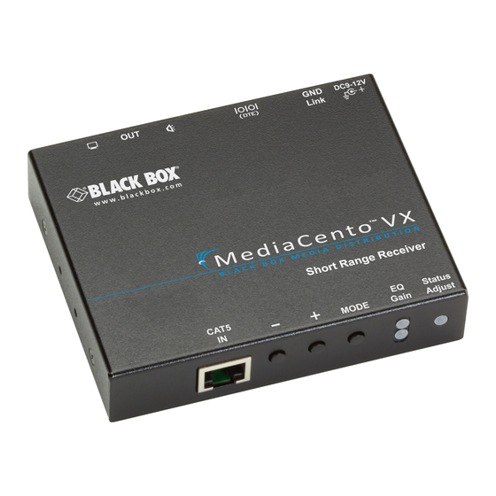
Page 19: Standard Receiver (Avx-Vga-Tp-Srx) And Long-Range
Chapter 2: Overview 2.4.4 Standard Receiver (AVX-VGA-TP-SRX) and Long-Range Receiver (AVX-VGA-TP-LRX) Figure 2-4. AVX-VGA-TP-SRX or AVX-VGA-TP-LRX front, top, and back panels. 724-746-5500 | blackbox.com Page 19... - Page 20 Chapter 2: Overview Table 2-4. AVX-VGA-TP-SRX or AVX-VGA-TP-LRX components. Number Component Description HD15 connector Connect to a VGA monitor. Audio jack Connect to a speaker. RJ-45 jack Connect to a transmitter/cascadable receiver. Push button: - Minus Press once to decrease one level. Push button: + Plus Press once to increase one level.
-
Page 21: Cascadable Long-Range Receiver (Avx-Vga-Tp-Csrx)
Chapter 2: Overview Table 2-4 (Continued). AVX-VGA-TP-SRX or AVX-VGA-TP-LRX components. Number Component Description Barrel connector Links to power supply. Ground terminal Connect to common ground. 2.4.5 Cascadable Long-Range Receiver (AVX-VGA-TP-CSRX) Figure 2-5. AVX-VGA-TP-CSRX front and back panels. 724-746-5500 | blackbox.com Page 21... - Page 22 Chapter 2: Overview Table 2-5. AVX-VGA-TP-CSRX components. Number Component Description Cascade off: Connect to a VGA monitor. HD15 connector Cascade on: Connect to a transmitter’s VGA input port. Audio jack Connect to a transmitter’s audio input port. RJ-45 jack Connect to a transmitter/cascadable receiver. RJ-45 jack Connect to a receiver/cascadable receiver.
-
Page 23: Slide Switches (Avx-Vga-Tp-Tx-4, Avx-Vga-Tp-Tx-8, Avx-Vga-Tp-Csrx)
Connect to a serial device for serial Serial port extension. Barrel connector Links to power supply. Ground terminal Connect to common ground. Slide switch Cascade ON/OFF 2.4.6 Slide Switches (AVX-VGA-TP-TX-4, AVX-VGA-TP-TX-8, AVX-VGA-TP-CSRX) Figure 2-6. Slide switches. 724-746-5500 | blackbox.com Page 23... - Page 24 Chapter 2: Overview NOTE: The Master/Slave slide switch is on 4- and 8-port transmitters (AVX-VGA-TP-TX-4, AVX-VGA-TP-TX-8) only. The Cascade slide switch is on 4- and 8-port transmitters (AVX-VGA-TP-TX-4, AVX-VGA-TP-TX-8) and the cascadable receiver (AVX-VGA-TP-CRX). Table 2-6. Slide switches on the 4-/8-Port Transmitter.
-
Page 25: Installation
Chapter 3: Installation 3. Installation WARNING: • Before installation, power off all devices that will be connected to this system. • Make sure that all devices you will connect are properly grounded. • Place cables away from fluorescent lights, air conditioners, and machines that are likely to generate electrical noise. -
Page 26: 1-Port Transmitter + Cascadable Receiver + Receiver (Non-Cascaded Application)
Chapter 3: Installation 3.2 1-Port Transmitter + Cascadable Receiver + Receiver (Non-Cascaded Application) HD15 CAT5 CAT5 CAT5 CAT5 CAT5 Figure 3-2. Connection pattern for 1-Port Transmitter + Cascadable Receiver + Receiver (Non-Cascaded Application). 724-746-5500 | blackbox.com Page 26... -
Page 27: 1-Port Transmitter + Cascadable Receiver + Receiver (Cascaded Application)
Chapter 3: Installation 3.3 1-Port Transmitter + Cascadable Receiver + Receiver (Cascaded Application) Figure 3-3. Connection pattern for 1-Port Transmitter + Cascadable Receiver + Receiver (Cascaded Application). 724-746-5500 | blackbox.com Page 27... -
Page 28: 8-Port Transmitter + Cascadable Receiver + Receiver (Non-Cascaded Application)
Chapter 3: Installation 3.4 4-/8-Port Transmitter + Cascadable Receiver + Receiver (Non-Cascaded Application) Figure 3-4. Connection pattern for 4-/8-Port Transmitter + Cascadable Receiver + Receiver (Non-Cascaded Application). 724-746-5500 | blackbox.com Page 28... -
Page 29: 8-Port Transmitter + Cascadable Receiver + Receiver (Cascaded Application)
Chapter 3: Installation 3.5 4-/8-Port Transmitter + Cascadable Receiver + Receiver (Cascaded Application) Figure 3-5. Connection pattern for 4-/8-Port Transmitter + Cascadable Receiver + Receiver (Cascaded Application). 724-746-5500 | blackbox.com Page 29... -
Page 30: Operation
Chapter 4: Operation 4. Operation 4.1 Video Adjustment on Receiver/Cascadable Receiver Unit To optimize the video signal associated with various cable lengths, users may adjust the video compensation on the Receiver/Cascadable Receiver Unit. It follows the order in sequence of: EQ—>Gain—>Skew (Red—>Green—>Blue)—>EQ—> Gain…... -
Page 31: Edid Setting On Transmitter
Chapter 4: Operation 4.2 EDID Setting on a Transmitter In some cases, display problems may occur because of incorrect EDID communication between the display monitor and the unit or inappropriate EDID data programmed by display manufacturers. The EDID Copy function enables the system to either read the necessary EDID information from the unit or copy EDID from EDID-compliant displays. -
Page 32: Factory Default Setting On Transmitters And Receivers
Chapter 4: Operation 4.3 Factory Default Settings on Transmitters and Receivers To restore the transmitters and receivers to the default settings, follow these steps. 4.3.1 Factory Default Setting on the Transmitter STEP 1: Press and hold the “EDID Copy” button. STEP 2: Apply power to the transmitter. -
Page 33: Led Indicators
Chapter 5: LED Indicators 5. LED Indicators Table 5-1. 1-Port Transmitter LEDs. Status Description Lights when the transmitter is connected to an Link Green active receiver Green Power on (no video source input) Power on and video source detected (source input Status Blue detected);... - Page 34 Chapter 5: LED Indicators Table 5-2 (Continued). 4-/8-Port Transmitter LEDs. Status Description Green Power on (no video source input) Power on and video source detected (source input detected); LED turns Blue green six seconds after unplugging the source Emits blue with green Source detected (local audio output flashing once is off)
- Page 35 Chapter 5: LED Indicators Table 5-3. Receiver LEDs. Status Status Power on Link Green CAT5 connection detected Green Power on (no video source input) Power on and video source detected (source input detected); LED turns Blue green six seconds after unplugging the source Emits blue with green Source detected (local audio output...
-
Page 36: Serial Interface
Chapter 6: Serial Interface 6. Serial Interface NOTE: The MediaCento VX management software can be found on the Black Box Web site (www.blackbox.com). Navigate to one of the product pages by entering “MediaCento VX” into the search text box. You will find the software user manual and software download link under “Resources”... -
Page 37: Appendix A. Cat5 Cables
Appendix A: CAT5 Cables Appendix A. CAT5 Cables The extender pair requires a piece of unshielded twisted-pair (UTP) CAT5 cable. The cable should be wired according to the TIA/EIA 568B standard shown below. Table A-1. RJ-45 pinout. Wire Color Pair White/Orange Orange White/Green... -
Page 38: Appendix B. Control Cable Rj-11/Db9F Pinout
Appendix B: Control Cable RJ-11/DB9F Pinout Appendix B. Control Cable RJ-11/DB9F Pinout Table B-1. RJ-11/DB9F control cable pinout. RJ-11M DB9F 724-746-5500 | blackbox.com Page 38... -
Page 39: Appendix C. Text-Based Rs-232 Protocol Of Mediacento Vx
Appendix C: Text-Based RS-232 Protocol Appendix C: Text-based RS-232 Protocol of MediaCento ™ RS-232 Communication setting: Baud rate: 38400 Data bit: 8 Parity bit: 0 Stop bit: 1 Flow control: none Letter case: none The command set has the following format (Command is ASCII format). (a1.a2.a3.a4.a5.a6)XXX=n,m[CR] a1.a2.a3.a4.a5.a6 (Optional) The Address packet of the destination device node, variable length, with... - Page 40 Appendix C: Text-Based RS-232 Protocol (30.10.00), a Repeater — The node on the TX port 1 of node (30.10) (30.10.00.00), a Receiver — The node on the TX port 1 of node (30.10.00) [CR] carriage return ASCII code (hex value = 0x0D), the end of command packet [LF] line feed ASCII code ( hex = 0x0A ) [ESC] Escape ASCII code For example,...
- Page 41 Appendix C: Text-Based RS-232 Protocol Command List Table C-1. Command list. Command Set Description Status Returned VEN[CR] Enable video VDIS[CR] Disable video AEN[CR] Enable audio ADIS[CR] Disable audio REN[CR] Enable RS-232 RDIS[CR] Disable RS232 BEN[CR] Enable Buzzer output (refer to Error Code List in Table BDIS[CR] Disable Buzzer output...
- Page 42 Appendix C: Text-Based RS-232 Protocol Table C-1 (Continued). Command list. Status Command Set Description Returned GAIN+[CR] Set Gain level increase GAIN-[CR] Set Gain level decrease RSKW+[CR] Set Red channel de-skew increase RSKW-[CR] Set Red channel de-skew decrease GSKW+[CR] Set Green channel de-skew increase GSKW-[CR] Set Green channel de-skew decrease BSKW+[CR]...
- Page 43 Appendix C: Text-Based RS-232 Protocol Table C-2. Node with Branch Broadcast Set Command List. Command Set Description Status Returned BS_VEN[CR] Branch control video on BS_VDIS[CR] Disable video BS_AEN[CR] Enable audio BS_ADIS[CR] Disable audio BS_REN[CR] Enable RS-232 BS_RDIS[CR] Disable RS-232 BS_BEN[CR] Enable Buzzer output (refer to Error Code List in Table C-4)
- Page 44 Appendix C: Text-Based RS-232 Protocol Table C-3. Node with Branch Temporarily Control Command List. Status Command Set Description Returned TEMP_VEN[CR] Temporarily control video on TEMP_VDIS[CR] Temporarily control video off TEMP_V_OFF[CR] Temporarily control video cancel TEMP_AEN[CR] Temporarily control audio on TEMP_ADIS[CR] Temporarily control audio off TEMP_A_OFF[CR] Temporarily control audio cancel...
- Page 45 Appendix C: Text-Based RS-232 Protocol Table C-3 (Continued). Node with Branch Temporarily Controlling Command List. Command Set Description Status Returned Temporarily control audio, video, Refer to error list TEMP_XDIS[CR] RS-232, Buzzer off in Table C-4. Temporarily control audio, video, Refer to error list TEMP_X_OFF[CR] RS-232, Buzzer cancel in Table C-4.
- Page 46 NOTES 724-746-5500 | blackbox.com Page 46...
- Page 47 NOTES 724-746-5500 | blackbox.com Page 47...
- Page 48 724-746-5500 or blackbox.com. About Black Box Black Box provides an extensive range of networking and infrastructure products. You’ll find everything from cabinets and racks and power and surge protection products to media converters and Ethernet switches all supported by free, live 24/7 Tech support available in 30 seconds or less.
Need help?
Do you have a question about the AVX-VGA-TP-TX and is the answer not in the manual?
Questions and answers