Table of Contents
Advertisement
INSTALLATION MANUAL
AIR CONDITIONER (SPLIT TYPE)
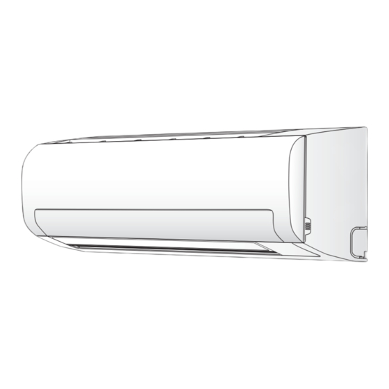
Indoor unit
42NQ009~012 Series
Outdoor unit
38NY009~012 Series
ENGLISH
ESPAÑOL
FRANÇAIS
ITALIANO
DEUTSCH
PORTUGUÊS
POLSKI
ČESKY
PУCСКИЙ
HRVATSKI
MAGYAR
TÜRKÇE
NEDERLANDS
ΕΛΛΗΝΙΚΑ
SVENSKA
SUOMI
NORSK
DANSK
ROMÂNĂ
БЪЛГАРСКИ
EESTI
LATVISKI
SLOVENČINA
SLOVENŠČINA
Advertisement
Table of Contents

Summary of Contents for Carrier 42NQ009-012 Series
-
Page 1: Installation Manual
INSTALLATION MANUAL ENGLISH AIR CONDITIONER (SPLIT TYPE) ESPAÑOL FRANÇAIS ITALIANO DEUTSCH PORTUGUÊS POLSKI ČESKY PУCСКИЙ HRVATSKI MAGYAR TÜRKÇE NEDERLANDS ΕΛΛΗΝΙΚΑ SVENSKA SUOMI NORSK DANSK Indoor unit Outdoor unit ROMÂNĂ 42NQ009~012 Series 38NY009~012 Series БЪЛГАРСКИ EESTI LATVISKI SLOVENČINA SLOVENŠČINA... - Page 2 CONTENTS CONTENIDOS SOMMAIRE PRECAUTIONS FOR SAFETY ............ 1 PRECAUCIONES SOBRE SEGURIDAD ........1 MESURES DE SÉCURITÉ ............1 INSTALLATION DIAGRAM OF INDOOR AND DIAGRAMA DE INSTALACIÓN DE LA UNIDAD INTERIOR Y PLAN D’INSTALLATION DES UNITÉS INTÉRIEURE ET OUTDOOR UNITS ............... 2 EXTERIOR ...................
- Page 3 Also, make sure the equipment is properly earthed. • Appliance shall be installed in accordance with national wiring regulations. If you detect any damage, do not install the unit. Contact your Carrier dealer immediately. CAUTION • Exposure of unit to water or other moisture before installation could result in electric shock.
-
Page 4: Optional Installation Parts
INSTALLATION DIAGRAM OF INDOOR AND OUTDOOR UNITS INSTALLATION DIAGRAM OF INDOOR AND OUTDOOR UNITS 42NQ009 42NQ012 For the rear left and left piping Hook Installation plate Wall Insert the cushion between the indoor unit and wall, and tilt the indoor unit for better operation. -
Page 5: Remote Control
INDOOR UNIT INDOOR UNIT When the installation plate is directly mounted Installation Place on the wall 1. Securely fi t the installation plate onto the wall by screwing it in the upper and • A place which provides the spaces around the indoor unit as shown in the lower parts to hook up the indoor unit. -
Page 6: Piping And Drain Hose Installation
(3) Slightly open the lower part of the front panel, then pull the upper part of the 42NQ009 Terminal block Cord clamp front panel toward you to remove it from the rear plate. Earth line Terminal cover Connecting 80 mm (4) After removing the front panel, remove the power cord connect cover and cable 10 mm... -
Page 7: Indoor Unit Fixing
How to remove the drain cap • Carefully arrange pipes so that any pipe does not stick out of the rear Clip the drain cap by needle-nose plate of the indoor unit. pliers and pull out. • Carefully connect the auxiliary pipes and connecting pipes to one another and cut off the insulating tape wound on the connecting pipe to How to fi... -
Page 8: Installation Place
OUTDOOR UNIT OUTDOOR UNIT • Tightening torque of fl are pipe connections Installation Place Flare at The operating pressure of R410A indoor unit side is higher than that of R22 (approx. • A place which provides the spaces around the outdoor unit as shown in the diagram 1.6 times). -
Page 9: Gas Leak Test
Packed valve handling precautions Stripping length of the connecting cable • Open the valve stem all the way out, but do not try to open it beyond the stopper. Terminal block • Securely tighten the valve stem cap with torque in the following table: 100 mm Terminal screw 1(L)


Need help?
Do you have a question about the 42NQ009-012 Series and is the answer not in the manual?
Questions and answers