Advertisement
INSTALLATION MANUAL
AIR CONDITIONER (SPLIT TYPE)
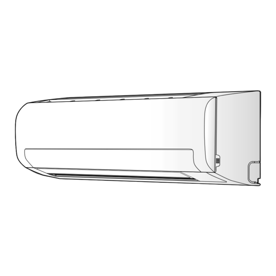
Indoor unit
42NQ018, 024 Series
Outdoor unit
38NY018, 024 Series
1110651131 (COVER_F).indd 1
1110651131 (COVER_F).indd 1
ENGLISH
ENGLISH
ESPAÑOL
FRANÇAIS
ITALIANO
DEUTSCH
PORTUGUÊS
POLSKI
ČESKY
PУCСКИЙ
HRVATSKI
MAGYAR
TÜRKÇE
NEDERLANDS
ΕΛΛΗΝΙΚΑ
SVENSKA
SUOMI
NORSK
DANSK
ROMÂNĂ
БЪЛГАРСКИ
EESTI
LATVISKI
SLOVENČINA
SLOVENŠČINA
1110651131
2/4/09 11:01:22 AM
2/4/09 11:01:22 AM
Advertisement
Table of Contents

Summary of Contents for Carrier 42NQ024
-
Page 1: Installation Manual
INSTALLATION MANUAL ENGLISH ENGLISH AIR CONDITIONER (SPLIT TYPE) ESPAÑOL FRANÇAIS ITALIANO DEUTSCH PORTUGUÊS POLSKI ČESKY PУCСКИЙ HRVATSKI MAGYAR TÜRKÇE NEDERLANDS ΕΛΛΗΝΙΚΑ SVENSKA SUOMI NORSK DANSK Indoor unit ROMÂNĂ 42NQ018, 024 Series БЪЛГАРСКИ Outdoor unit EESTI 38NY018, 024 Series LATVISKI SLOVENČINA SLOVENŠČINA 1110651131 1110651131 (COVER_F).indd 1... - Page 2 CONTENTS CONTENIDOS SOMMAIRE PRECAUTIONS FOR SAFETY ............1 PRECAUCIONES SOBRE SEGURIDAD........1 MESURES DE SÉCURITÉ ............1 INSTALLATION DIAGRAM OF INDOOR AND DIAGRAMA DE INSTALACIÓN DE LA UNIDAD PLAN D’INSTALLATION DES UNITÉS INTÉRIEURE ET INTERIOR Y EXTERIOR ..............2 EXTÉRIEURE................2 OUTDOOR UNITS ...............2 Piezas de Instalación Opcional ..........2 Pièces d’Installation en Option ..........2 Optional Installation Parts ............2 UNIDAD INTERIOR..............3...
- Page 3 ΠΕΡΙΕXOΜΕΝΑ INHOUDSOPGAVE INNEHÅLL ΠΡOΦΥΛΑΞΕΙΣ ΑΣΦΑΛΕΙΑΣ ............1 VEILIGHEIDSVOORZORGEN .............1 SÄKERHETSANVISNINGAR ............1 ∆ΙΆΓΡΑΜΜΑ ΕΓΚΑΤΆΣΤΑΣΗΣ ΤΗΣ ΕΣΩΤΕΡΙΚΉΣ ΚΑΙ INSTALLATIESCHEMA VOOR BINNEN- EN INSTALLATIONSSCHEMA FÖR INOMHUS- OCH ΕΞΩΤΕΡΙΚΉΣ ΜOΝΆ∆ΑΣ ............2 BUITENMODULES ..............2 UTOMHUSENHETEN ..............2 Προαιρετικά Eξαρτήµατα Eγκατάστασης ......2 Optionele Onderdelen .............2 Valfria Installationskomponenter..........2 ΕΣΩΤΕΡΙΚΉ ΜOΝΆ∆Α ...............3 BINNENMODULE ................3 INOMHUSENHETEN ..............3 Σηµείο...
- Page 4 Also, make sure the equipment is properly earthed. • Appliance shall be installed in accordance with national wiring regulations. If you detect any damage, do not install the unit. Contact your Carrier dealer immediately. CAUTION • Exposure of unit to water or other moisture before installation could result in electric shock.
-
Page 5: Optional Installation Parts
INSTALLATION DIAGRAM OF INDOOR AND OUTDOOR UNITS INSTALLATION DIAGRAM OF INDOOR AND OUTDOOR UNITS For the rear left and left piping Hook Installation plate Wall Insert the cushion between the indoor unit and wall, and tilt the indoor unit for better operation. Do not allow the drain hose to get slack. - Page 6 INDOOR UNIT INDOOR UNIT Mounting the installation plate Installation Place Anchor bolt holes • A place which provides the spaces around the indoor unit as shown in the diagram Hook • A place where there are no obstacles near the air inlet and outlet •...
- Page 7 1. Die-cutting front panel slit Wiring Connection Cut out the slit on the leftward or right side of the front panel for the left or right connection and the slit on the bottom left or right side of the front panel for the bottom left or right connection with a pair of nippers.
-
Page 8: Indoor Unit Fixing
NOTE Information If the pipe is bent incorrectly, the indoor unit may unstably be set on the wall. The lower part of indoor unit may fl oat, After passing the connecting pipe through the pipe hole, connect the due to the condition of piping and you connecting pipes to the auxiliary pipes and wrap the facing tape around them. -
Page 9: Refrigerant Piping Connection
1. Connect the charge hose from the manifold valve to the service port of Refrigerant Piping Connection the packed valve at gas side. 2. Connect the charge hose to the port of the vacuum pump. 3. Open fully the low pressure side handle of the gauge manifold valve. Flaring 4. -
Page 10: Gas Leak Test
Stripping length of the connecting cable Model 18 Class 24 Class Power source 50Hz, 220 – 240 V Single phase Terminal block Maximum running current Plug socket & fuse rating 4 mm (H07RN-F or 245 IEC66) Power cord or 3.5 mm (AWG-12) Terminal screw Earth line... -
Page 11: Test Operation
Test Operation To switch the TEST RUN (COOL) mode, press RESET button for 10 seconds. (The beeper will make a short beep.) Hi POWER FILTER TIMER OPERATION RESET RESET button Auto Restart Setting This product is designed so that, after a power failure, it can restart automatically in the same operating mode as before the power failure.


Need help?
Do you have a question about the 42NQ024 and is the answer not in the manual?
Questions and answers