Table of Contents

Related Manuals for Audiovox UCD101


Summary of Contents for Audiovox UCD101
- Page 1 OWNER’S MANUAL Mobile Audio System PLL Synthesizer Stereo Radio Digital Compact Disc Player Automatic Memory Storing Full Detachable Panel Preset Equalization Auxiliary Input Function Remote Control (OPTIONAL) 8800-C03012-00...
-
Page 2: Table Of Contents
CONTENTS Installation ........... 3 CD operation ........11 Take out screw before installation ..3 Switching to CD mode ...... 11 DIN Front-Mount (Method A)....3 Selecting tracks......... 11 Installing the unit ....... 3 Pausing playing......... 11 Removing the unit ......4 Previewing all tracks ...... -
Page 3: Installation
INSTALLATION Notes: TAKE OUT SCREW BEFORE INSTALLATION Choose the mounting location where Before install the unit, please remove the the unit will not interfere with the two screws. normal driving function of the driver. Take out screw Before finally installing unit, before installation. -
Page 4: Removing The Unit
INSTALLATION back of the unit in place. Use the they will go (with the notches facing up) supplied hardware (Hex Nut (M5mm) into the appropriate slots at the middle and Spring Washer) to attach one end of left and right sides of the unit. Then slide the strap to the mounting bolt on the the sleeve off the back of the unit. -
Page 5: Din Rear-Mount (Method B)
INSTALLATION To fasten the unit to the factory radio 4. Lift the top of the outer trim ring then pull mounting brackets. it out to remove it. Align the screw holes on the bracket with 5. Insert both of the supplied keys into the the screw holes on the unit, and then slots at the middle left and right sides of tighten the screws (5x5mm) on each side. -
Page 6: Using The Detachable Front Panel
USING THE DETACHABLE FRONT PANEL Precautions when handling REMOVING THE FRONT PANEL 1. Do not drop the front panel. 1. Press the release button (RELEASE) 2. Do not put pressure on the display or on the front panel and pull off the front control buttons when removing or panel. -
Page 7: Wiring Connection
WIRING CONNECTION FOR 4x25W OR 4x40W SYSTEM MAIN UNIT (BLACK) AUX IN CABLE Rch RED ANTENNA CONNECTOR Lch WHITE (FOR AUX IN VERSION ONLY) FUSE IGNITION SWITCH (ACC+) (BROWN) FUSE MEMORY Rch RED FRONT RCA CABLE YELLOW BACK-UP (B+) Lch WHITE BLACK GROUND (B-) (GREY) -
Page 8: For 4X7W Or 2X25W System
WIRING CONNECTION FOR 4x7W OR 2x25W SYSTEM MAIN UNIT (BLACK) Rch RED AUX IN CABLE ANTENNA CONNECTOR Lch WHITE (FOR AUX IN VERSION ONLY) IGNITION FUSE SWITCH (ACC+) FUSE MEMORY YELLOW (BROWN) Rch RED BACK-UP (B+) FRONT RCA CABLE BLACK Lch WHITE GROUND (B-) (GREY) -
Page 9: Operation
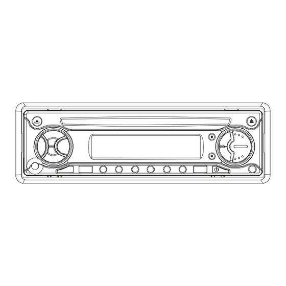
OPERATION LOCATION OF KEYS 19 27 21 22... -
Page 10: Switching On/Off The Unit
OPERATION SWITCHING ON/OFF THE UNIT REMOTE SENSOR (OPTIONAL) Switch on the unit by pressing any button Point the remote control handset to the (except RELEASE button (7) and remote sensor IR (26). Press the function button (4)). When system is on, press keys on the handset to control the system. -
Page 11: Automatic Memory Storing& Program Scanning
OPERATION the display. appears. AUTOMATIC MEMORY STORING & SELECTING TRACKS PROGRAM SCANNING Press button (17) or button (16) to move to the previous track or the - Automatic memory storing following track. Track number shows on Press AS/PS button (18) for several display. -
Page 12: Disc Notes
OPERATION cause files loss. And we won’t answer for c. Do not play a CD-RW which has been the direct or indirect damages caused by written for more than 5 times. losing files. DISC NOTES A. Notes on discs: 1. Attempting to use non-standard shape discs (e.g. -
Page 13: Specification
SPECIFICATION GENERAL Power Supply Requirements : DC 12 Volts, Negative Ground Chassis Dimensions : 178 (W) x 160 (D) x 50 (H) Tone Controls : ±10 dB Bass (at 100 Hz) : ±10 dB Treble (at 10 kHz) Maximum Output Power Version V : 4x7 watts or 2x25 watts Version Z... -
Page 14: Trouble Shooting
TROUBLE SHOOTING Before going through the checklist, check wiring connection. If any of the problems persist after checklist has been made, consult your nearest service dealer. Symptom Cause Solution The car ignition switch is power supply No power. not on. connected to the car accessory circuits, but the engine is not moving, switch the ignition key...
Need help?
Do you have a question about the UCD101 and is the answer not in the manual?
Questions and answers