Table of Contents
Advertisement
INSTALLER: Leave this manual with the appliance.
CONSUMER: Retain this manual for future reference.
WARNING:
FIRE OR EXPLOSION HAZARD
Failure to follow safety warnings exactly could result in serious
injury, death, or property damage.
- Do not store or use gasoline or other ammable vapors and
liquids in the vicinity of this or any other appliance.
- WHAT TO DO IF YOU SMELL GAS
• Do not try to light any appliance.
• Do not touch any electrical switch; do not use any phone
in your building.
• Leave the building immediately.
• Immediately call your gas supplier from a neighbour's phone.
Follow the gas supplier's instructions.
• If you cannot reach your gas supplier call the fire department.
- Installation and service must be performed by a qualified
installer, service agency or the gas supplier.
This appliance may be installed in an aftermarket
permanently located, manufactured home (USA only)
or mobile home, where not prohibited by local codes.
This appliance is only for use with the type of gas
indicated on the rating plate. This appliance is
not convertible for use with other gases, unless a
certifi ed kit is used.
This appliance is suitable for installation in a
bedroom or bed sitting room.
WARNING:
If the information in these
instructions is not followed exactly, a fi re
or explosion may result causing property
damage, personal injury or death.
170915-44
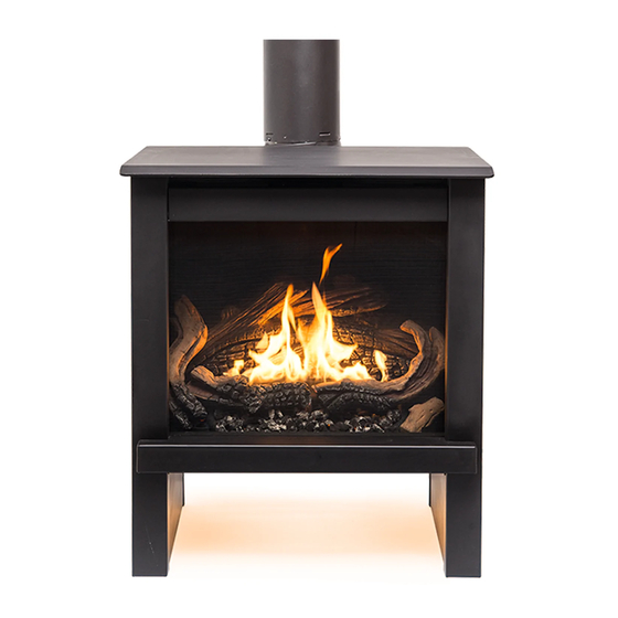
MODEL: TN24
SERIES: A
DIRECT VENT GAS STOVE
INSTALLATION AND OPERATING
INSTRUCTIONS
TN24.BODYA
SERIAL #
5055.48-A
Advertisement
Table of Contents

Related Manuals for True North TN24


Summary of Contents for True North TN24
- Page 1 WARNING: If the information in these instructions is not followed exactly, a fi re or explosion may result causing property MODEL: TN24 damage, personal injury or death. SERIES: A DIRECT VENT GAS STOVE INSTALLATION AND OPERATING...
-
Page 2: Table Of Contents
Replacement parts ..........39 TN24 Co-Linear venting ........18 Wiring diagram ........... 40 Venting components ......... 19 Rating label location ......... 41 TN24 Gas stove rear components ....20 DANGER HOT GLASS WILL CAUSE BURNS. DO NOT TOUCH GLASS UNTIL COOLED. -
Page 3: Important Note For The Commonwealth Of Massachusetts
A copy of all installation instructions for all Product Approved side wall horizontally vented gas fuelled equipment, all venting instructions, all parts lists for venting instructions, and/or all venting design instructions shall remain with the ap- pliance or equipment at the completion of the installation. TN24.BODYA 5055.48-A 170915-44... -
Page 4: Owners Information
Do not use the gas stove if any part has been under water. Immediately call a qualified service techni- cian to inspect the gas stove and to replace any part of the control system and any gas control which has been under water. TN24.BODYA 5055.48-A 170915-44... -
Page 5: Safety
It is normal for gas stoves fabricated from steel to give off some expansion and/or contraction noises during the start up or cool down cycle. Similar noises are found with your furnace heat exchanger or cook stove oven. TN24.BODYA 5055.48-A 170915-44... -
Page 6: Manufactured (Mobile) Home
Owners Information Manufactured (Mobile) Homes n some jurisdictions, the TN24 gas stove may be installed in Manufactured Homes after the “first sale”. Consult local codes for approval. The gas stove must be fastened in place. Install in accordance with the current standard Mobile Homes, CAN/CSA Z240 MH (in CANADA), and the Manufacturer’s Home Construction and Safety Standard, Title 24 CFR, Part 3280 or the current... -
Page 7: Remote Control Operation
(Figure 1) & (Figure 2). Figure 1: P rofl ame 2 remote control handset. Figure 2: P rofl ame 2 LCD screen detail. TN24.BODYA 5055.48-A 170915-44... - Page 8 If the batteries of the receiver or remote transmitter are low or depleted, the gas stove can be turned off manually using the ON/OFF switch located on the battery holder at the rear of the TN24 (Figure 65) & (Figure 66). This will bypass the remote transmitter.
- Page 9 Figure 11: Smart flame Figure 12: Smart flame the set point, press the up or down arrow keys until function. adjusting the desired set point temperature is displayed on temperature. the LCD screen of the remote transmitter (Figure 12). TN24.BODYA 5055.48-A 170915-44...
- Page 10 Key (Figure 1) to index to the light bulb icon (Figure 17). The intensity of the output can be adjusted through six (6) levels. Use the Up/Down Arrow Keys (Figure 1) to adjust the output level (Figure 18). A single “beep” will confi rm reception of the command. TN24.BODYA 5055.48-A 170915-44...
-
Page 11: Warnings And Cautions
In no way is the from the gas stove burner when operating the enclosure to be tampered with or opened. remote system or activating manual bypass of Disconnect from line voltage before performing the remote system. any maintenance. TN24.BODYA 5055.48-A 170915-44... -
Page 12: Maintenance
Viewing glass may be cleaned as necessary with fireplace glass cleaner. b) Exterior finish may be cleaned with mild soap and water. CAUTION: Do not use abrasive cleaners on glass or any other part of the gas stove. Do not clean glass when hot. TN24.BODYA 5055.48-A 170915-44... -
Page 13: Lighting Instructions
Owners Information Lighting Instructions Figure 20: True North lighting instructions. TN24.BODYA 5055.48-A 170915-44... -
Page 14: Installer Information
TN24 Gas Stove Dimensions Dimensions Hight 29 11/16 inches Width 25 inches Depth 19 3/16 inches Height to center of Flue Outlet 24 inches 25” 19 3/16” 29 11/16” 24” 24” 17 3/4” Figure 21: True North 24 dimensions. TN24.BODYA 5055.48-A 170915-44... -
Page 15: Clearances To Combustibles
Only Horizontal venting requirement is that 4” the oor be stable and strong enough to Horizontal venting support the stove 4” Vertical venting 4” 1” Figure 23: True North 24 common locations & minimum allowances TN24.BODYA 5055.48-A 170915-44... -
Page 16: Vent Terminal Clearance
* as speci ed in CGA B149 Installation Codes, Note: local Codes or Regulation may require different clearances * for U.S.A. Installations follow the current National Fuel Gas Code, ANSI Z223.1 Figure 25: Vent terminal minimums table. TN24.BODYA 5055.48-A 170915-44... -
Page 17: Tn24 Co-Axial Venting Chart
Every venting configuration is different, and the damper setting may need slight adjustment. (See page 31 for damper adjustment). NO VENTING OPTION VENTING HORIZONTAL RUN Figure 26: True North 24 Co-axial venting chart. TN24.BODYA 5055.48-A 170915-44... -
Page 18: Tn24 Co-Linear Venting
For larger chimneys, ashing will need to be constructed according to local building codes. NOTE: If venting the TN24 through an existing replace opening using a co-axial to co-linear adapter, the customer will have a couple of aesthetic options which include:... -
Page 19: Venting Components
4DT-HC 46DVA-HC Snorkel Termination Cap 4ST14 4DST14 SV4STC14 4DT-ST14 46DVA-SNK14 4ST36 4DST36 SV4STC36 4DT-ST36 46DVA-SNK36 Horizontal Termination Kit 4HTK 4DHTKA SV0HK 4DT-HKA 46DVA-KHA 4DHTKB SV0HK2 4DT-HKB 46DVA-KHC Vertical Termination Kit 4DVTK SV0FK 4DT-VKC SV0FAK/SV0FBK Figure 29: 4” x 6⅝” Rigid Pipe Components Cross Reference Chart. TN24.BODYA 5055.48-A 170915-44... -
Page 20: Tn24 Gas Stove Rear Components
Figure 30: Co-axial venting components. TN24 Gas Stove rear components Right blower fan Left blower fan Battery bay Electrical IFC Module connection Venturi connection adjustment Gas valve Figure 31: True North 24 rear side components. TN24.BODYA 5055.48-A 170915-44... -
Page 21: Gas And Electrical Connection
(Figure 32). See “Gas Supply” on page 32 of this manual for gas supply requirements. Electrical connection An IEC power cord is provided for connection to a standard wall outlet. Figure 32: True North 24 gas & electrical connections. TN24.BODYA 5055.48-A 170915-44... -
Page 22: Screen Mesh Removal
Figure 33: True North 24 gas stove with packaging. Screen mesh removal Figure 34: True North 24 top cover. Figure 36: True North 24 mesh Figure 35: True North 24 mesh removal. - Page 23 The large number one log (Figure 39) comes wrapped separately from the smaller logs (Figure 40) & (Figure 41). The logs will be assembled in a specific order along with the glowing embers, glass door and mesh screen. Figure 41: Smaller logs in styrofoam. TN24.BODYA 5055.48-A 170915-44...
-
Page 24: Log Set Installation
(indicated by the arrow). Once the 2nd log is mounted to the first log, position the lower portion of 2nd log so that it is located close to the pilot without covering it, and as close to the front of the firebox without interfering with the glass door once installed. TN24.BODYA 5055.48-A 170915-44... - Page 25 Figure 47: 4th log placement. 6. Place 5th log as shown in (Figure 48) making sure that the log does not cover the holes of the back row of the burner. Figure 48: 5th log placement. TN24.BODYA 5055.48-A 170915-44...
-
Page 26: Glass Door Installation
Insert and tighten the bolts to secure the glass door frame to the firebox. Figure 52: Glass panel position tab. CAUTION: Over-tightening the wing nuts could result in the glass door fracturing. TN24.BODYA 5055.48-A 170915-44... -
Page 27: Screen Mesh Installation
(Figure 55) shows the screen mesh resting at a point where it is higher than the firebox frame and glass door frame immediately to its right. (Figure 56) shows the screen mesh properly installed. Figure 56: proper orientation of screen mesh. Figure 55: Improper orientation of screen mesh. TN24.BODYA 5055.48-A 170915-44... - Page 28 t into position of the screen mesh holder. Figure 58: Screen mesh holder. Return the top cover to its proper position. Screen mesh Figure 59: Screen holder in correct position. TN24.BODYA 5055.48-A 170915-44...
-
Page 29: Accent Lighting Glass Plates
Installer Information Accent Lighting Glass Plates The TN24 Gas Stove comes with an assortment of glass plates of various colours. Accent lighting is controlled via the remote control transmitter included with the TN24 Gas Stove (Figure 1 on page 7). The glass plate tray is located underneath the stove (Figure 60) and is held in place by two wing nuts - one on each side of the tray. -
Page 30: Ifc Module
Initializing the System for the fi rst time 1. Install 4 AA batteries into the TN24 battery bay (Figure 65) located on the rear side of the TN24 (Figure 68) . Install the ON/OFF switch cover (Figure 66) over top of the battery bay. Make sure that the selection switch is on the “Remote”... -
Page 31: Damper Adjustment
Damper adjustment is located under the top cladding cover plate. Figure 69: True north 24 Damper. Burner Installation Burner Installation/Removal Installation Fit the burner over the orifice (Figure 70) & (Figure 71) and set so that the screw holes on both sides of the burner are making full contact with the back panel (Figure 72). -
Page 32: Gas Supply
Check local codes for additional requirements. Turn on the gas supply and check that all connections are tight and leak free. Gas Pressure Check Gas pressure requirements TN24 Input Pressure Natural Gas Propane Gas Orifice Output... -
Page 33: Gas Pressure Testing Procedure
Pilot Flame Adjustment The pilot flame level can be adjusted by turning the adjustment screw located on the valve in (Figure 76) Pilot adjustment Main gas Pilot Figure 74: True north 24 Pilot assembly. screw solenoid solenoid Figure 76: Gas control valve. -
Page 34: Propane Conversion
To convert the gas stove from natural gas to propane the (TN24.LPKITA) kit is required. This kit comes with new pilot and burner orifi ces as well as a new pressure modulator for the valve. -
Page 35: Fan Replacement
See replacement parts list (page 39) for Figure 82: Fan motor Figure 83: Fan motor part numbers. 1026 (left). 1027 (right). NOTE: Fan manufacturers part numbers are as follows: SA-25L-1027 = Right fan SA-25L-1026 = Left Fan TN24.BODYA 5055.48-A 170915-44... -
Page 36: Fire Box Panel Installation
Installer Information Fire Box Panel Installation Installation Figure 85: True north interior panels. 1. Insert back panel so that it is sitting on the ledge at the back of the fi rebox as shown in (Figure 86). 2. Insert side panels so that they are sitting on top of the lower back panel support as shown in (Figure 87). -
Page 37: Screen Mesh Replacement
Installer Information Screen Mesh Replacement Removal Figure 92: True North 24 top Figure 93: Screen mesh holder Figure 94: Screen mesh cover removal. raised. removal. Remove the top cover as shown in (Figure 92) . Raise the mesh cover as shown in (Figure 93). and lift the mesh screen out (Figure 94). -
Page 38: Glass Door Replacement
Glass door retainer frame moved away from posts prior to lifting and removing. Figure 97: True North mesh Figure 98: True North 24 glass door removed. tilted forward. 1. Remove the mesh screen as described on “Screen mesh replacement” on page 37. -
Page 39: Replacement Parts
True North Control Tray Complete ......TN24.CNTTRAY True North Panel Set Painted ........TN24.PNLSETA True North Burner ............. TN24.BURNA True North Log Set with Embers ......TN24.LOGSETA True North Blower Right (SA-25L-1027) ....TN24.BLOWR True North Blower Left (SA-25L-1026) ..... TN24. BLOWL True North Light Housing with Bulb ...... -
Page 40: Wiring Diagram
Installer Information Wiring Diagram LAMP COMFORT Caution: Label all wires prior to disconnection when servicing controls. Wiring errors can cause improper and dangerous operation. Verify proper operation after servicing. TN24.BODYA 5055.48-A 170915-44... -
Page 41: Rating Label Location
DU GAZ NATUREL DU GAZ LP MODEL/ Minimum supply pressure / Pression minimum d’alimentation: 5.0 in/wc / 5.0 po/c.e. 12.5 in/wc / 12.5 po/c.e. TN24 (1.25 kPa) (3.11 kPa) MODELE: (For the purpose of input adjustment / dans le but de régler l’alimenation) Maximum supply pressure / Pression maximum d’alimentation:... - Page 42 TN24.BODYA 5055.48-A 170915-44...
- Page 43 TN24.BODYA 5055.48-A 170915-44...
- Page 44 © 2015 Copyright Pacific Energy Fireplace Products LTD Reproduction, adaptation, or translation without prior written permission is prohibited, except as allowed under the copyright laws. For technical support, please contact your retailer Web site: www. pacificenergy.net 2975 Allenby Rd., Duncan, BC V9l 6V8...
Need help?
Do you have a question about the TN24 and is the answer not in the manual?
Questions and answers