Table of Contents
Advertisement
INSTRUCTIONS
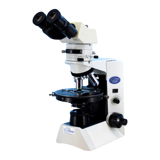
CX31-P
POL ARIZING MICROSCOPE
This instruction manual is for the Olympus Polarizing Microscopes Model CX31-P. To ensure the
safety, obtain optimum performance and to familiarize yourself fully with the use of this microscope,
we recommend that you study this manual thoroughly before operating the microscope. Retain this
instruction manual in an easily accessible place near the work desk for future reference.
A X 7 3 4 9
This publication is printed on 100% recycled paper
Advertisement
Table of Contents

Related Manuals for Olympus CX31-P


Summary of Contents for Olympus CX31-P
- Page 1 CX31-P POL ARIZING MICROSCOPE This instruction manual is for the Olympus Polarizing Microscopes Model CX31-P. To ensure the safety, obtain optimum performance and to familiarize yourself fully with the use of this microscope, we recommend that you study this manual thoroughly before operating the microscope. Retain this instruction manual in an easily accessible place near the work desk for future reference.
-
Page 3: Table Of Contents
CX31-P CONTENTS Correct assembly and adjustments are critical for the microscope to manifest its full performance. If you are going to assemble the microscope by yourself, please read Chapter 9, “ASSEMBLY” (Pages 23 to 26). For the assemblies of the modules for which instruction manuals are available, refer to their instruction manuals. - Page 4 POLARIZED LIGHT OBSERVATION 15-18 5-1 Preparation ......................................15-17 Cross-Nicol Adjustment Centering the Rotary Stage Adjusting the Centering Adapter for Objective 5-2 Orthoscopic Observation ................................. 18 5-3 Conoscopic Observation ................................18 SPECIFICATIONS OPTICAL CHARACTERISTICS TROUBLESHOOTING GUIDE 21-22 ASSEMBLY 23-26 PROPER SELECTION OF THE POWER SUPPLY CORD ..............27-28...
-
Page 5: Safety Precautions
4. Always use the power cord provided by Olympus. If no power cord is provided, please select the proper power cord by referring to the section “PROPER SELECTION OF THE POWER SUPPLY CORD”... -
Page 6: Maintenance And Storage
Warning label position Bottom of microscope frame ture in lamp bulb replacement If the warning label is stained or peeled off, contact Olympus. Getting Ready 1. A microscope is a precision instrument. Handle it with care and avoid subjecting it to sudden or severe impact. - Page 7 CX31-P Caution If the microscope is used in a manner not specified by this manual, the safety of the user may be imperiled. In addition, the equipment may also be damaged. Always use the equipment as outlined in this instruction manual.
-
Page 8: Module Nomenclature
MODULE NOMENCLATURE ?The modules shown below are merely the typical examples. For other applicable modules that are not shown, please consult the latest catalogues or Olympus. Eyepieces · WHN10X · WHN10X-H · CROSS WHN10X Observation Tube · WHB10X · U-BI30P ·... -
Page 9: Controls
CX31-P CONTROLS }If you have not yet assembled the microscope, read Chapter 9, “ASSEMBLY” (pages 23 to 26) first. · The illustration shows the microscope together with the U-BI30P binocular observation tube for polarizing observation U-PA intermediate tube for polarizing observation and U-CTAD centering adapter for objective lens. -
Page 10: Summary Of Polarized Light Observation Procedure
SUMMARY OF POLARIZED LIGHT OBSERVATION PROCEDURE }This chapter describes the procedure for polarized light observation using the U-PA intermediate tube for polarizing observation. For the procedure using the U-OPA or U-KPA, refer to the instruction manual for the intermediate tube in use. * The operations marked * are not required when the U-CTAD centering adapter for objective lens is not used. - Page 11 CX31-P }In general biological microscopy, the analyzer, Observation method Objective Bertrand’s lens Bertrand’s lens and test plate are not necessary and Orthoscopy 4x to 100x should be disengaged from the light path. When higher brightness is required. remove the polar-...
-
Page 12: Microscope Frame
In this case, minimize the diaphragm diameter. Fig. 4 Using the Filters (Fig. 5) · Drop one or stacked 45 mm filter(s) 1 into the window lens on the frame. }For the filter models, consult the latest catalogues or Olympus. Fig. 5... -
Page 13: Focusing Module
CX31-P 4-2 Focusing Module Adjusting the Coarse Adjustment Knob Rotation Tension (Fig. 6) 1. The tension of the coarse focus adjustment knob is adjustable. Insert the tip of a large flat-blade screwdriver into the groove 2 on the tension adjustment ring 1 and rotate the ring. Rotating it clockwise (in the direction of the arrow) increases the tension and counterclockwise decreases the tension. -
Page 14: Using The Eye Shades
Using the Eye Shades (Fig. 10) When Wearing Eyeglasses Use with the eye shades in the normal, folded-down position. This will prevent the eyeglasses from being scratched. When Not Wearing Eyeglasses Extend the folded eye shades in the direction of the arrow to prevent extraneous light from entering between the eyepieces and eyes. -
Page 15: Intermediate Tube For Polarizing Observation (U-Pa)
CX31-P 4-4 Intermediate Tube for Polarizing Observation (U-PA) }For the description on the U-OPA or U-KPA intermediate tube for polarizing observation, refer to the instruction manual provided with it. Using the Bertrand’s Lens (Fig. 13) 1. To engage the Bertrand’s lens into the light path, slide the Bertrand’s lens engaging/focusing knob 1 horizontally so that the ) (IN) indication comes on the front. -
Page 16: Rotary Stage
4-5 Rotary Stage Placing Specimen on the Stage When the specimen holder is used (Fig. 14) Place the specimen on the center and hold it with the specimen holder. When the mechanical stage (U-FMP) is used (Fig. 15) How to attach the mechanical stage Fit the guide pins on the bottom of the U-FMP into the holes on the stage top, and tighten the clamping screw 1 of the U-FMP using an Allen Fig. -
Page 17: Condenser
CX31-P 4-6 Condenser Centering the Field Iris Diaphragm (Figs. 17 & 18) }When using the U-CTAD centering adapter for objective lens, perform the operation in Adjusting the Centering Adapter for Objective Lens in section 5-1 (page 17) before proceeding to the following steps. -
Page 18: Immersion Objective
4-7 Immersion Objective Using the Immersion Objective (Fig. 20) # Always use immersion oil supplied by Olympus. Using oil other than designated may degrade the condenser lens surface. 1. Focus on the specimen using all objectives, starting from the lowest- power objective to higher-power objective. -
Page 19: Operation
CX31-P POLARIZED LIGHT OBSERVATION 5-1 Preparation As the microscope cannot manifest full performance in polarized light observation if the optical adjustments are not perfect, be sure to perform the following adjustments before observation. Disengage the specimen, quarter-wave plate, sensitive tint plate, etc. from the light path before proceeding. - Page 20 2. Align the center of the reference plane of the orientation plate with the cross lines of the eyepiece, and engage the analyzer in the light path to achieve the cross-Nicol condition. 3. While observing the oriented plate, rotate the stage till the orientation plate looks darkest, and clamp the stage rotation there. Rotate the stage so that the bottom edge of the dark orientation plate is adjacent to the cross line.
-
Page 21: Adjusting The Centering Adapter
CX31-P Adjusting the Centering Adapter (Figs. 25 to 27) for Objective Lens }This adjustment brings the center of conoscopic image accurately on the center of the field of view. It also ensures the rotation center of the rotary stage to be matched perfectly after objective switching. -
Page 22: Orthoscopic Observation
5-2 Orthoscopic Observation }Use an objective between 4x to 100x. 1. When the U-PA intermediate tube for polarizing observation is used, set the Bertrand’s lens engaging/focusing knob to the ( (OUT) position to disengage the Bertrand’s lens from the light path. 2. -
Page 23: Specifications
CX31-P SPECIFICATIONS Specifications Item Optical system UIS2/UIS (Universal Infinity System) optical system (infinity correction) Objectives Polarized light objectives of the PlanN4X-P and AchN10X-P to 100XO-P Eyepieces WHN10X, WHN10-X, CROSS WHN10X. WHB10X, WHB10-X. Field number 20. Field number 22. Micrometer disk can be inserted. -
Page 24: Optical Characteristics
OPTICAL CHARACTERISTICS – UIS series objectives not listed here can also be combined with this microscope. – The following table shows the optical characteristics of Objective type combinations of eyepieces and objectives. The figure Magnification on the right shows the performance data engraved on Number aperture (NA) the objectives. -
Page 25: Troubleshooting Guide
Use immersion oil. mersion objective. Bubbles are mixed in the immersion oil. Remove the bubbles. The specified immersion oil is not used. Use the immersion oil supplied by Olympus. Clean them thoroughly. The specimen is dirty. The eyepieces and/or condenser are dirty. - Page 26 Problem Cause Remedy Page 2. Focus adjustment mechanism a) The tension of coarse adjustment The coarse adjustment knob rotation Loosen the ring to adjust to proper knob it too high. tension adjustment ring is set too tight. tension. b) The stage lowers by its own weight The coarse adjustment knob rotation Tighten the ring to adjust to proper or focusing is lost due to slippage...
-
Page 27: Assembly
The module model numbers shown in the following diagram are merely the typical examples. For the modules with which the model numbers are not given, please consult the latest catalogues or Olympus. # When assembling the microscope, make sure that all parts are free of dust and dirt, and avoid scratching any parts or touching glass surfaces. - Page 28 9-2 Detailed Assembly Procedures Installing/Replacing the Lamp Bulb (Fig. 29) 1. Place the microscope frame on the back and pull the lock knob 1 on the bottom to open the lamp bulb replacement cover. 2. Hold the halogen lamp bulb 2 without taking it out of the polyethylene bag so as not to stain the bulb with fingerprints or stains, and push the bulb all the way into the pin holes on the socket 3.
- Page 29 CX31-P Mounting the U-PA Intermediate (Fig. 31) Tube for Polarizing Observation }For the mounting method of other intermediate tube models, refer to their instruction manuals. 1. Fully loosen the observation tube clamping screw 1 of the microscope frame using the Allen wrench provided with it.
- Page 30 ” (OFF) before connect- ing the power cord. Always use the power cord provided by Olympus. If no power cord is provided, please select the proper power cord by referring to the section “PROPER SELECTION OF THE POWER SUPPLY CORD” at the end of this instruction manual.
-
Page 31: Proper Selection Of The Power Supply Cord
If no power supply cord is provided, please select the proper power supply cord for the equipment by referring to “ Specifications ” and “ Certified Cord ” below: CAUTION: In case you use a non-approved power supply cord for Olympus products, Olympus can no longer warrant the electrical safety of the equipment. - Page 32 Table 2 HAR Flexible Cord APPROVAL ORGANIZATIONS AND CORDAGE HARMONIZATION MARKING METHODS Alternative Marking Utilizing Printed or Embossed Harmoniza- Black-Red-Yellow Thread (Length tion Marking (May be located on Approval Organization of color section in mm) jacket or insulation of internal wir- ing) Black Yellow...
- Page 33 MEMO...
- Page 34 MEMO...
- Page 36 2-43-2, Hatagaya, Shibuya-ku, Tokyo, Japan Postfach 10 49 08, 20034, Hamburg, Germany 2 Corporate Center Drive, Melville, NY 11747-3157, U.S.A. One Corporate Drive, Orangeburg, NY 10962, U.S.A. 491B River Valley Road, #12-01/04 Valley Point Office Tower, Singapore 248373 2-8 Honduras Street, London EC1Y OTX, United Kingdom. 31 Gilby Road, Mt.
Need help?
Do you have a question about the CX31-P and is the answer not in the manual?
Questions and answers