Yamaha THR100HD Owner's Manual
Thr series
Hide thumbs
Also See for THR100HD:
- Owner's manual (125 pages) ,
- Owner's manual (24 pages) ,
- Owner's manual (25 pages)
Table of Contents
Advertisement
THR
Guitar Amplifier
THR100HD / THR100H
MODERN
LEAD
I
CRUNCH
CLEAN
SOLID
I + II
MODERN
LEAD
II
CRUNCH
CLEAN
SOLID
MODERN
LEAD
CRUNCH
CLEAN
SOLID
Series
BOOSTER
GAIN
MASTER
BASS
BOOSTER
GAIN
MASTER
BASS
BOOSTER
GAIN
MASTER
BASS
MIDDLE
TREBLE
PRESENCE
REVERB
MIDDLE
TREBLE
PRESENCE
REVERB
MIDDLE
TREBLE
PRESENCE
REVERB
THR100HD
VOLUME
INPUT I
VOLUME
INPUT II
THR100H
VOLUME
INPUT
Advertisement
Table of Contents

Related Manuals for Yamaha THR100HD


Summary of Contents for Yamaha THR100HD
- Page 1 Series Guitar Amplifier THR100HD / THR100H THR100HD BOOSTER GAIN MASTER BASS MIDDLE TREBLE PRESENCE REVERB VOLUME INPUT I MODERN LEAD CRUNCH CLEAN SOLID I + II BOOSTER GAIN MASTER BASS MIDDLE TREBLE PRESENCE REVERB VOLUME INPUT II MODERN LEAD CRUNCH...
- Page 2 Explanation of Graphical Symbols Explication des symboles The lightning flash with arrowhead symbol within an equilateral triangle is intended to alert the user to the presence of uninsulated “dangerous voltage” within the product’s enclosure that may be of sufficient magnitude to constitute a risk of electric shock to persons. L’éclair avec une flèche à...
- Page 3 2) this device must accept any interference received including interference that may cause undesired operation. See user manual instructions if interference to radio reception is suspected. * This applies only to products distributed by YAMAHA CORPORATION OF AMERICA. (FCC DoC) FCC INFORMATION (U.S.A.) 1.
- Page 4 This device complies with Part 15 of the FCC Rules. Operation is subject to the following two conditions: (1) this device may not cause harmful interference, and (2) this device must accept any inter- ference received, including interference that may cause undesired operation. This Class B digital apparatus complies with Canadian ICES-003.
-
Page 5: Table Of Contents
THR series Guitar Amplifier THR100HD / THR100H Owner’s Manual Index PRECAUTIONS ...........6 Features ...........9 Package Contents ........9 Names And Functions ......... 10 Connecting the Cabinet ....... 16 Power Connection ........19 Using the Effect Loop ......... 19 Using the Footswitch ........20 More Detailed Settings ....... -
Page 6: Precautions
Then have the device • Use only the supplied power cord/plug. inspected by Yamaha service personnel. • Check the electric plug periodically and remove any - The power cord or plug becomes frayed or dam- dirt or dust which may have accumulated on it. - Page 7 Keep at least 5cm of space above, left and right sides, and behind the device. Yamaha cannot be held responsible for damage caused by improper use or modifications to the device, or data that is lost or destroyed. The name plate is located on the bottom of the unit. Always turn the power off when the device is not in use.
- Page 8 • Copying of the software is strictly prohibited. property, follow the notices below. • This product incorporates and bundles computer n Handling and Maintenance programs and contents in which Yamaha owns copyrights or with respect to which it has license to • Do not use the device in the vicinity of a TV, radio, use others’ copyrights. Such copyrighted materials stereo equipment, mobile phone, or other electric include, without limitation, all computer software, devices. Otherwise, the device, TV, or radio may...
-
Page 9: Features
• The THR100HD features a Dual Amplifier design that lets you create sound with two amplifiers from a single head unit. This feature is also useful for providing separate amplification for two electric guitars, letting two people perform simultaneously. -
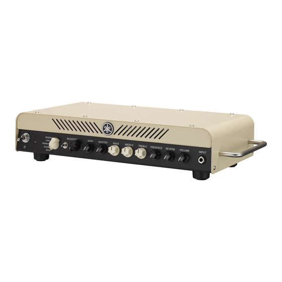
Page 10: Names And Functions
Names And Functions THR100HD l Front Panel BOOSTER GAIN MASTER BASS MIDDLE TREBLE PRESENCE REVERB VOLUME INPUT I MODERN LEAD CRUNCH CLEAN SOLID I + II BOOSTER GAIN MASTER BASS MIDDLE TREBLE PRESENCE REVERB VOLUME INPUT II MODERN LEAD CRUNCH... -
Page 11: Power Switch
INPUT I/II to the output circuit. Connect the guitar to this jack. I+II ... The signal from the guitar connected to the On the THR100HD, the Amp Select switch e INPUT I jack is sent to both Amp I (top) and assigns signal flow from INPUT I and INPUT Amp II (bottom). The outputs of both Amp I II to either Amp I (up position) or Amp II (lower and II are sent to the output circuit. - Page 12 Adjusts the tonal character of the preamp n VCM Technology section. Turn the knob clockwise to enhance The five virtual amp types found in the THR100 are mid-range frequencies. produced using Yamaha’s proprietary VCM Technology, a newly developed amp modeling technology that faithfully reproduces the operating characteristics of controls and !1 TREBLE distinctive tone of each individual amp. VCM also lets you Adjusts the tonal character of the preamp switch the virtual power tubes in the power amp section via section.
- Page 13 6V6: Tube used in small American combo amps delivers distortion even at a low volume level. * The THR100 amp does not incorporate physical tubes in its design. Instead, it utilizes Yamaha’s EL84: Tube often used in British combo amps VCM Technology to faithfully reproduce the delivers a soft drive.
-
Page 14: Speaker Out
Tube Class Switch Connects the cabinet to the amp. Selects the operating type of the tube selected On the THR100HD, jack 1 and jack 2 signals with the Tube Type Selector !5 . differ according to the Amp Select switch e setting and whether the SPEAKER OUT 2 jack CLASS A: is connected to a cable. - Page 15 This is a stereo mini phone jack for headphones. Like the LINE OUT jack @2 , the signal for this jack passes through the speaker simulator. The jack is stereo but output to both L and R terminals is the same (mono). On the THR100HD, both LINE OUT I and II jack signals are mixed and sent to both L and R terminals. * Connecting a plug to the PHONES jack stops output to the SPEAKER OUT 1/2 jacks. Output to the LINE OUT I/II jacks is not affected.
-
Page 16: Connecting The Cabinet
CAUTION THRC112 Using the wrong setting can damage the speakers and the amp. Settings on the Yamaha THRC212 Cabinet will change power rating and impedance requirements for the cabinet. Please read the THRC212 Owner’s Manual carefully and make the appropriate settings. - Page 17 100W INPUT 8Ω 100W 8Ω THRC112 THRC112 THRC112 THR100HD Amp Select Switch Setting and the Amp I Amp II Signal Output to the Cabinet Sound Sound l Amp Select Switch = I Amp I (top) sound is output. THR100HD Amp Select Switch Setting and the...
- Page 18 The THR100HD’s Amp Select Switch setting and signal output to the cabinet are the same as in Example 3. Rated output for the THR100HD is 50W + 50W when the SPEAKER OUT 1, 2 jacks each have a separate cabinet connected.
-
Page 19: Power Connection
Power Cord (supplied) CAUTION For safe operation, always connect the ground wire. Using the Effect Loop Use the EFFECT LOOP SEND/RETURN jacks to On the THR100HD, the SEND/RETURN jacks are connect an external effector. (Diagram 1) stereo (TRS), with Amp I assigned to the Tip and Amp II assigned to the Ring. (Diagram 2) You can switch the Effect Loop ON/OFF using the To connect an external effect to Amp I only, use a included footswitch. (→ page 20) monaural phone cable. -
Page 20: Using The Footswitch
Using the Footswitch Some of the amp’s functions and switch settings can be controlled with your feet using the supplied footswitch. THR100HD THR100H q [THR100HD] AMP I/II t FX LOOP Switches the front panel Amp Select switch Switches the signal from the rear panel EFFECT setting between AMP I and II. LOOP SEND/RETURN jack ON/OFF. Both Amp I and Amp II are switched simultaneously. -
Page 21: More Detailed Settings
“THR HD_ ing or shutting down, as well as corruption or even H Utility” and the required driver from the Yamaha loss of data. If the device or computer does freeze, web site below. - Page 22 More Detailed Settings n Updating the Amplifier’s * The “Yamaha Steinberg USB Driver” may be updated without notice. Please visit the above Firmware website for the latest details and updates. Updates for the amp’s internal firmware provide 2. Install the “Yamaha Steinberg USB Driver” in improvements to the device.
-
Page 23: Troubleshooting
Is an instrument properly connected to the Allow the amplifier to cool down then switch INPUT jack? the power ON again. If the thermal protection THR100HD: Is the instrument connected to system activates again, unplug the power cord the INPUT II jack? If only a single instrument and contact the Yamaha dealer from whom is being used, it must be connected to the you purchased the device. -
Page 24: Specifications
AC100V - 240V, 50/60 Hz THR100HD AMP I, II Common: Power Switch, Amp Select Power Consumption Switch, Impedance Switch, Power Rating THR100HD: 60 W Switch, GND/LIFT Switch THR100H: 40 W AMP I, II One Each: Amp Type Selector, BOOSTER Switch, BOOSTER, GAIN, MAS-... - Page 25 ZQ05310-1 版次 : R0 Printed in China...
Need help?
Do you have a question about the THR100HD and is the answer not in the manual?
Questions and answers