Advertisement
Quick Links
INSTALLATION AND MAINTENANCE INSTRUCTIONS
PS24LO and PS24LOW Strobes
Specifications
PS24LO/LOW Strobe
Operating Voltage:
Maximum Current Drain at
listed voltage:
Minimum Light Output at
100% viewing angle:
Temperature Range:
NOTE: This strobe is listed to the 16 to 33 VDC UL limits.
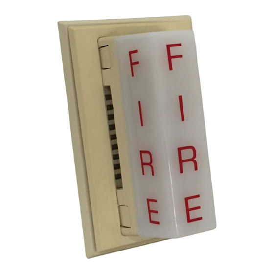
Figure 1:
60%
100% 100%
(REF)
7%
F
I
60%
R
E
7%
A0208-00
Installation with PA400 Sounder
The optional strobes are interconnected to the PA400 by first
removing the two mounting screws from the sounder. Use a small
screwdriver to punch out the skinned-over areas as indicated in
Figure 2. Install the adapter plate on top of the sounder and screw
the combined sounder and adapter plate to the electrical outlet
box. Make sure field wiring terminals are oriented in the upward
position when mounted in the outlet box. Next, slide the strobe
directly into the slots in the plates. The positive solder lug may
be colored red or marked with a plus sign (+). This lug must be
in the slot closest to the field wiring terminals. Grasp the catch
area on each end of the strobe and squeeze while applying inward
force. Make sure the strobe catches fully engage the slots in the
adapter plate and that no gap appears at the interface between the
strobe and adapter plate.
D200-51-00
16-33 VDC
25 mA
1.5 candela (see Fig. 1)
0°C to 49°C (32°F to 120°F)
60%
100%
60%
3825 Ohio Avenue, St. Charles, Illinois 60174
The Products to which this manual applies may
be covered by one or more of the following
U.S. Patent numbers: 5,546,293 and 5,488,462
General Information
The National Fire Protection Association has published codes,
standards, and recommended practices for the installation and
use of the above appliances. Therefore, the installer must be
familiar with these requirements, with local codes, and any spe-
cial requirements of the authority having jurisdiction.
Model PS24
The model PS24 optional strobe can be added to the SSK451
multi-signaling or PA400 accessories.
Installation Notes
The wiring must be in compliance with all codes and must not be
of such length or wire size that would cause the appliance to oper-
ate outside of its published specifications. The appliances must also
be tested after installation in accordance with the duct detector
manufacturer's test procedure.
NOTE: Do not loop wires under terminal screws. Wires connecting
the device to the panel must be broken at the device screw
terminal in order to maintain electrical supervision.
Figure 2:
A0206-00
1
A Division of Pittway
1-800-SENSOR2, FAX: 630-377-6495
www.systemsensor.com
A0205-00
I56-2716-001R
Advertisement

Subscribe to Our Youtube Channel
Related Manuals for System Sensor PS24LO


Summary of Contents for System Sensor PS24LO
- Page 1 INSTALLATION AND MAINTENANCE INSTRUCTIONS PS24LO and PS24LOW Strobes A Division of Pittway 3825 Ohio Avenue, St. Charles, Illinois 60174 1-800-SENSOR2, FAX: 630-377-6495 www.systemsensor.com The Products to which this manual applies may be covered by one or more of the following U.S. Patent numbers: 5,546,293 and 5,488,462 Specifications PS24LO/LOW Strobe Operating Voltage: 16-33 VDC Maximum Current Drain at listed voltage: 25 mA Minimum Light Output at 100% viewing angle: 1.5 candela (see Fig. 1) Temperature Range: 0°C to 49°C (32°F to 120°F) NOTE: This strobe is listed to the 16 to 33 VDC UL limits.
- Page 2 The PS24LO strobe will be mounted on top of the sounder, Installation with SSK451 Multi-signaling Accessory This optional strobe can be purchased separately and is on the left-hand side of the SSK451. Place one mounting spacer between the SSK451 and the strobe adapter plate easily added to the SSK451 accessory. at each screw attachment location. Attach the adapter plate, spacer and SSK451 to the left-hand side of the double-gang elec- trical outlet box with two mounting screws. RED TERMINAL ON TOP Slide the strobe terminals directly into the two slots in the Figure 3: adapter plate and SSK451. The positive lug, which will be col- ored red, must be installed into the top slot. Grasp the catch area on the top of the strobe and squeeze while applying inward force. Repeat for the catch area on the bottom of the strobe. Make sure the strobe catches fully engage into the slots in the adapter plate and that no gap appears at the interface between the strobe and adapter plate. Optional SMOKE Strobe Lens NOTE: To meet the code requirements of certain jurisdictions, an optional SMOKE lens can be purchased separately. SMOKE lens, wall mount PS12/24SLENSW SMOKE lens, ceiling mount PS12/24SLENSC H0485-00 Please follow the instructions enclosed with the lens for proper installation of the lens to the strobe.
Need help?
Do you have a question about the PS24LO and is the answer not in the manual?
Questions and answers