
Subscribe to Our Youtube Channel
Related Manuals for ESP MAGPRO96


Summary of Contents for ESP MAGPRO96
- Page 1 ANALOGUE ADDRESSABLE FIRE PANEL MAGPRO96 INSTALLATION AND PROGRAMMING MANUAL 1293...
-
Page 2: Table Of Contents
3.7.6 Language selection ....................................46 3.7.7 Delay (T1) ......................................46 3.7.8 Printer Menu ......................................46 3.8 Restore Defaults ......................................46 4. MAINTENANCE ........................................47 4.1 Maintenance Menu ......................................47 4.2 Time introducing ......................................47 Addressable Fire Panel MAGPRO96 - Installation and Programming Manual... - Page 3 STANDARDS AND CONFORMITY The addressable fire alarm control panel MAGPRO96 is designed and certified according and with conformity to EN 54 – 2/4 standard. Conforms and approved in accordance with CPR (Construction Products Regulation). Addressable Fire Panel MAGPRO96 - Installation and Programming Manual...
-
Page 4: Introduction
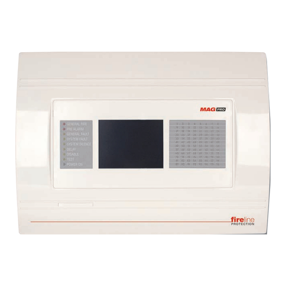
1. INTRODUCTION 1.1 General Description MAGPRO96 is an analogue addressable fire panel with maximum coverage of 96 zones and connecting 1 to 4 loops. The panel supports communication protocol MAGPRO (MAGPRO96-L250 loop controller). In the configuration of the MAGPRO96 panel can be implemented up to 4 MAGPRO96-L250 loop controllers. -
Page 5: General Technical Specifications
- For 3 loops configuration: 435 mA DC - For 4 loops configuration: 510 mA DC ATTENTION: Do not instal the fire panel near power electromagnetic fields (radio equipment, elec- tric motors, etc.)! Addressable Fire Panel MAGPRO96 - Installation and Programming Manual... - Page 6 - General Power Supply: ....2A, T Type - Outputs:..........0,3A, PTC Type - Battery: ..........7.5A, PTC Type List of the additional components, included in the set of the fire panel MAGPRO96: Resistor 10K ±5%, 0,25W Anchor 6х30mm Fuse 2А, T type 5x20mm (for the mains power supply) Screw М4х40 Cross slot DIN7985...
-
Page 7: Installation
(see Figure 17) BUT DO NOT apply the main electrical supply at this stage. • Position the battery in an upright position and fix the metal clamp - Figure 10. Figure 4 Figure 5 Addressable Fire Panel MAGPRO96 - Installation and Programming Manual... -
Page 8: Flush Mounting (Option)
2.1.2 Flush Mounting (option) • Analogue-addressable fire panel MAGPRO96 is available for flush mounting. The accessory set contains two special hangers (see Figure 7) for flush wall mounting of the fire alarm panel on 25 mm thick drywall. • Use given on Figure 6 dimensions to outline and to cut the mounting hole in the drywall. -
Page 9: System Components
Clamp for supporting the main power Mains power supply opening. supply cable. Figure 10. Configuration of the basic modules in the system. Addressable Fire Panel MAGPRO96 - Installation and Programming Manual... -
Page 10: Output Module (I/O Module) And 4 Relay Module
2.2.3 Output Module (I/O Module) and 4 Relay Module The I/O Module (Figure 11a) is a basic part of the fire panel MAGPRO96, see the description of the terminals below. The 4 Relay Module is integrated onto the I/O Module and has 4 relays with programmable relay outputs. -
Page 11: Connecting Devices To The Outputs Module
0,3A. Before connecting the last sounder in the circuit, parallel to it must be added resistor 10k. Figure 13. Connecting of sounders. Addressable Fire Panel MAGPRO96 - Installation and Programming Manual... -
Page 12: Loop Expander
= 500mA. If the consumption ex- ceeds this value an over-load protection would be turned on. In the configuration of analogue-addressable fire panel MAGPRO96 could be mounted up to 4 loop controllers. Loop Expander 1 - Interface connector for connecting the Loop expander to the I/O Module. -
Page 13: Maximum Permissible Cable Length
The maximum length of the loop in the system could vary according to the cross-section and the ohmic resistance of the used cable. ATTENTION: MAGPRO96-L250 controller supports up to 250 devices, regardless of the type! To ensure the correct operation of the system is necessary to make some calculations in advance: 1. -
Page 14: Main Power Source
Input for connecting the Fault output of the external power supply. +13.8V External power supply input. Before the mains supply is switched on, check the correct connection of each loop, sounder or any other input or output. Addressable Fire Panel MAGPRO96 - Installation and Programming Manual... -
Page 15: Connecting Of The Accumulator Battery
- uPC Module, for control of the panel functions and operations. ATTENTION: Adjustment on the main board can be done from an authorized personnel only! Figure 19. Main Board with integrated Control Module. Addressable Fire Panel MAGPRO96 - Installation and Programming Manual... -
Page 16: Connecting A Heat Printer
The addressable fire alarm panel MAGPRO96 supports Canon 9 type external printers, models Kafka and Datecs. For connecting the MAGPRO96 panel to the heat printer you have to prepare a special cable for the purpose – connect two male DB9-DB9 (Datecs printer) or DB9-DIN5 (Kafka printer) type connectors as shown on Figure 20. -
Page 17: Connecting An Ajax Lan Communication Module
2.7 Network connection diagram It is possible to connect some individual MAGPRO96 fire panels in a network by means of a HUB and TCP/IP protocol - Figure 22. A supervisor PC, which could follow the current status of the individual fire panels, monitors the current panel state. -
Page 18: Programming
- see also The APPENDIX E on page 57. 3.0.3 Default Language The fire panel MAGPRO96 can support different languages of the programming menus. The factory default setting of the language is in English. You can change the language after the initial power-up as enter in sequence: Access 1 →... -
Page 19: Access Codes
MENU - Moves back to the Main Screen of the related access level. All access codes could be viewed and edited in the “Access Codes“ submenu based in “Panels“ menu, see also item 3.7.1. Addressable Fire Panel MAGPRO96 - Installation and Programming Manual... - Page 20 √ √ Software Revision View the software revision √ Display Calibration of the Display √ Review the activated insulators in the system (modules and View Insulator Act. √ built-in in devices) Addressable Fire Panel MAGPRO96 - Installation and Programming Manual...
-
Page 21: Programming Menu
Choosing the button “Restore Defaults” on the right side of the screen can restore all the factory settings. Button “Save” is for quick saving of the entered information. With the button “Exit” in the bottom left corner the user/installer can easy move one step back on the previous screen. Addressable Fire Panel MAGPRO96 - Installation and Programming Manual... -
Page 22: Devices
3.3 Devices The addressable fire panel MAGPRO96 supports periphery and loop devices. All “functional modules” connected to the control panel configuration are defined as Periphery Devices, and have spe- cial programming and setting. The Main board is not a periphery device. All addressable devices connected to loop expander are defined as Loop Devices. -
Page 23: Adding A New Periphery Device To The Panel
If a device is not responding you can remove it as choosing the REMOVE button. Fig. Screen 5 PSU Parameters (Power source) Fig. Screen 6 – OUT (I/O module + 4 Relay Expander Module) Addressable Fire Panel MAGPRO96 - Installation and Programming Manual... -
Page 24: Loop Devices
Should a different device type appear at the address of a saved device, the panel will generate “LOOP DEVICE TYPE ERROR”. For MAGPRO96-L250 loop controller first you need to remove wrong and then to save the new type of the device. - Page 25 • Loop Controller MAGPRO96-L250 The loop controller MAGPRO96-L250 automatically recognizes the types of devices in the loop. In addition the installer defines the additional parameters for every MAGPRO device according its type - see also the Appendix B - MAGPRO device types. The “SAVE” button (Fig. Screen 3) can be used for fast configuration of the device. Following this command, the panel sets up all detected loop and periphery devices by default.
- Page 26 • Smoke (%)/ Heat (°C) - Press the button to enter in a new screen for checking of the following current parameters: - T fire – Shows the operating temperature of the detector, in degrees centigrade. - Т – Shows the current temperature in the room, in degrees centigrade. Addressable Fire Panel MAGPRO96 - Installation and Programming Manual...
- Page 27 Attention: It is not allowed disabling the temperature and the optical parts at the same time! To save the new setting press the “Apply” button on the main screen of the device. Addressable Fire Panel MAGPRO96 - Installation and Programming Manual...
- Page 28 - LOW – Set in those cases when the number of the connected sounders to the loop is up to 60 (WS and WSS). To save the new setting press the “Apply” button on the main screen of the device. Addressable Fire Panel MAGPRO96 - Installation and Programming Manual...
- Page 29 - LOW – Set in those cases when the number of the connected sounders to the loop is up to 100 (DBS and DBSS). To save the new setting press the “Apply” button on the main screen of the device. Addressable Fire Panel MAGPRO96 - Installation and Programming Manual...
- Page 30 * Note: HIGH Sound Level - Up to 30 sounders WS and WSS type; Up to 30 sounders DBS and DBSS type. ** Note: LOW Sound Level - Up to 60 sounders WS and WSS type; Up to 100 sounders DBS and DBSS type. Addressable Fire Panel MAGPRO96 - Installation and Programming Manual...
- Page 31 Every pressing of “Disabling/ Enabling” button changes alternatively the parameter setting. Going back to the previous screen is with pressing the “MORE” button. Press the “Apply” button to save this settings. Addressable Fire Panel MAGPRO96 - Installation and Programming Manual...
- Page 32 To configure the inputs operation you have to go to menu INPUTS (SYSTEM - PROGRAMMING - INPUTS) - see the description of the menu in item 3.5. Press the “Apply” button to save this settings. Addressable Fire Panel MAGPRO96 - Installation and Programming Manual...
- Page 33 To configure the inputs operation you have to go to menu INPUTS (SYSTEM - PROGRAMMING - INPUTS) - see the description of the menu in item 3.5. Press the “Apply” button to save this settings. Addressable Fire Panel MAGPRO96 - Installation and Programming Manual...
- Page 34 To configure the outputs operation you have to go to menu OUTPUTS (SYSTEM - PROGRAMMING - OUTPUTS) - see the description of the menu in item 3.6. Press the “Apply” button to save this settings. Addressable Fire Panel MAGPRO96 - Installation and Programming Manual...
-
Page 35: Addressing Of Devices
The installer enters ADDRESSING - START SELF-ADDRESSING menu. The panel shows the first free address for every of the available MAGPRO96-L250 loops. Now the installer can start mount- ing detectors and modules one by-one. The panel will set the displayed address number to the mounted device and automatically proceeds with next free address in the system. -
Page 36: Change Address Menu
To perform self addressing, enter in the installer’s menu - ADDRESSING - START SELF ADDRESSING. The panel shows the first free address for every of the MAGPRO96-L250 loops. Now the installer can start mounting detectors and modules one by-one. The panel will set the displayed address number to the mounted device and automatically proceeds with next free address in the system. -
Page 37: Zones
Choose in sequence from the Main menu screen System - Programming - Zones. The MAGPRO96 addressable fire panel avails of 96 zones. The FIRE and PREALARM conditions are indicated by the help of the LED of the corresponding zone. In the PREALARM condition - the respective zone LED blinks and a warning message is displayed on the screen. -
Page 38: Inputs
Note: It is possible to enter addresses only of loop devices, which are INPuT type: detectors, call points, input- outputs modules! If the device if not an INPuT type a message is shown: “This device can not be used as Input!” Addressable Fire Panel MAGPRO96 - Installation and Programming Manual... - Page 39 - PANEL/ REPEATER Number. Enter a number from 1 to 32. All changed parameters are confirmed and saved by pressing the APPLY button in the upper left corner of the screen. Addressable Fire Panel MAGPRO96 - Installation and Programming Manual...
-
Page 40: Outputs
The working mode of the sounders at input activation is: - when the switch is pressed - one second sounders on, one second sounders off; - when the switch is released - the sounder is off. Addressable Fire Panel MAGPRO96 - Installation and Programming Manual... -
Page 41: Output Delay
3.6.7 Menu for selection of the inputs, controlling the outputs Fig. Screen 17. All changed parameters are confirmed and saved by pressing the APPLY button in the upper left corner of the screen. Addressable Fire Panel MAGPRO96 - Installation and Programming Manual... -
Page 42: Panel
Attention! There must be at least one code in the system with an access code 3! The program disal- lows editing a level of access (3) if it is the only one! Addressable Fire Panel MAGPRO96 - Installation and Programming Manual... -
Page 43: Network
From Network Settings menu can be programmed additionally panel IP, Netmask and IP-number of the Router, as and to be seen the panel MAC-address after choosing the MORE button - see Fig. Screen 20A. Fig. Screen 20A Addressable Fire Panel MAGPRO96 - Installation and Programming Manual... -
Page 44: Panels Menu
IP and network numbers, the panels with doubled numbers generate a Fault message. You can access to the Fault messages by pressing the Button Fault from the Panels menu. Addressable Fire Panel MAGPRO96 - Installation and Programming Manual... -
Page 45: Disable Menu
Choose button Sounders Mode from Panel menu to enter in this submenu - see Fig. Screen 18. The Installer has a possibility to set a group of parameters common for all sounders in the system. Fig. Screen 23 - Choosing a Sounders Mode. Addressable Fire Panel MAGPRO96 - Installation and Programming Manual... -
Page 46: Call Point Mode
“Apply“ button. 3.8 Restore Defaults In this menu the installer performs reset to default settings of the system configuration. The panel will ask for confirma- tion of the action. Addressable Fire Panel MAGPRO96 - Installation and Programming Manual... -
Page 47: Maintenance
- Fig. Screen 27. Use the APPLY button to confirm the settings. The desired date can be set with the buttons for selecting the day, month and year. Fig. Screen 27. Addressable Fire Panel MAGPRO96 - Installation and Programming Manual... -
Page 48: Daytime Mode
The Day time operating mode is indicated with icon in the system status field. All changed parameters are confirmed and saved by pressing the APPLY button in the upper left corner of the screen. Addressable Fire Panel MAGPRO96 - Installation and Programming Manual... -
Page 49: Output Delay Introduction
In Schedule mode the initial hour and minutes (the time when the delay is activated) and the end hour and minutes (the time when the delay is deactivated) are introduced. The times are set for every day of the week. During turned on “Delay” the LED is active. Addressable Fire Panel MAGPRO96 - Installation and Programming Manual... -
Page 50: Fire Output Delay
Choose “View Log” from the Maintenance Menu to enter in a screen for viewing the recorded events in the system. The addressable fire panel MAGPRO96 can show maximum 10 240 events, which could be viewed by date or number - Fig. -
Page 51: Zone Test Menu
Here the installer can perform operability test of the sounder outputs on the control panel’s PCB. To start the test press the “ON“ button. The sounder outputs will be activated together with the LED TEST on the control panel. To stop the test press the “OFF“ button. Addressable Fire Panel MAGPRO96 - Installation and Programming Manual... -
Page 52: Disable Introducing
By choosing a button with a device number the user/installer moves to menu for setting of the parameters of the respective device see Fig. Screen 8, part Programming. Addressable Fire Panel MAGPRO96 - Installation and Programming Manual... -
Page 53: Zone Disabling
From the menu for disabling introduction - Fig. Screen 35, the user/installer can disable or enable the monitored outputs of the MAGPRO96 fire panel - Sounder, Fire Brigade, Fire Protection and Fire Routing - Fig. Screen 38. Use the APPLY button to confirm your choice. -
Page 54: Display
The message “Calibration Unsuccessful!!!” will be displayed if the calibration has been unsuccessful, the newly intro- duced data will be ignored and after pressing of any part of the display, the program returns to the main menu. Fig. Screen 39. Addressable Fire Panel MAGPRO96 - Installation and Programming Manual... -
Page 55: Brightness Calibration
This is an information menu for reviewing the active insulators. To access this menu choose in sequence SYSTEM- MAINTENANCE-VIEW INSULATOR ACTIVE - Fig. Screen 41. The active insulator in the system are displayed as de- vice addresses in the field “Address” for MAGPRO96-L250 loops. Fig. Screen 41. -
Page 56: Instruction For Use
Used for accessing the alarm review window. The button contains a counter of the current alarms in the panel. • Faults Access button Used for accessing the error review window. • Warnings Access button Used for accessing the warnings review window. 5.2 Panel Status Icons Fig. Screen 43. Addressable Fire Panel MAGPRO96 - Installation and Programming Manual... -
Page 57: Panel Mode Icon
Dark grey The fire extinguishing output is delayed - delay is running prior to activation (programmable (Blinks) for every zone). The icon blinks and the countdown time until activation is displayed. Addressable Fire Panel MAGPRO96 - Installation and Programming Manual... -
Page 58: Messages
The “Evacuate” button is activated only in access levels 2 and 3. After it is pressed, the sounder and the programmable outputs will be activated, the “General Fire” LED lights up and a warning message is displayed. Note: The System Button is described in details in part Programming. Addressable Fire Panel MAGPRO96 - Installation and Programming Manual... -
Page 59: Appendix
Doubling of the IP address and the panel number (when two or more panels are number connected in a network). New Periphery Devices New periphery devices have been detected. Found New Loop Devices Found New loop devices have been detected. Addressable Fire Panel MAGPRO96 - Installation and Programming Manual... -
Page 60: Appendix B
4. Sounders • MAGPRO-WS - Wall mounted sounder • MAGPRO-WSS - Wall mounted sounder and strobe • MAGPRO-DbS - Base with built-in sounder • MAGPRO-DbSS - Base with built-in sounder and strobe Addressable Fire Panel MAGPRO96 - Installation and Programming Manual... -
Page 61: Appendix C
Appendix C - General Menu Structure Addressable Fire Panel MAGPRO96 - Installation and Programming Manual... -
Page 62: Appendix D
Appendix D Initial Start-up of the System Addressable Fire Panel MAGPRO96 - Installation and Programming Manual... -
Page 63: Appendix E
Appendix E “Two steps of alarming” Operation Algorithm Addressable Fire Panel MAGPRO96 - Installation and Programming Manual... - Page 64 Elite Security Products Ltd, Unit 7 Target Park, Shawbank Road, Lakeside, Redditch B98 8YN, UK Tel.: 01527 515150 http://www.espuk.com...
Need help?
Do you have a question about the MAGPRO96 and is the answer not in the manual?
Questions and answers