Table of Contents
Advertisement
Quick Links
Advertisement
Table of Contents

Related Manuals for Digitus DN-16084-1


Summary of Contents for Digitus DN-16084-1
- Page 1 4MP WDR Optical Zoom Bullet IP Camera User’s Manual DN-16084-1 Ver. 1.0...
-
Page 2: Table Of Contents
Table of Contents Overview ..........................2 Features ........................2 Package Contents ....................... 3 Dimensions ........................4 microSD Card Slot / Factory Default Button ..............5 Camera Cabling ........................6 All-in-One Cable ......................6 Connect Power ......................7 Connect Ethernet Cable....................7 Connect Alarm I/O ....................... -
Page 3: Overview
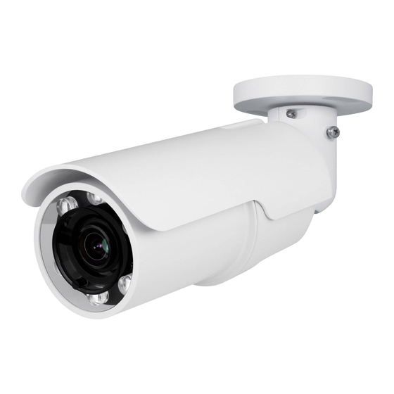
Overview DN-16084-1 equipped with an outstanding processing engine delivers 4K real-time streaming that provides 4 times details of Full HD resolution without sacrificing the frame rate. Software features, such as Privacy masks and ROI windows, further extend the range of camera application. The new generation built-in IR LED module emits sufficient infrared lights to light up the area under surveillance without the help of any additional lighting devices. -
Page 4: Package Contents
Package Contents Please check the package contains the following items listed below. Hyper IR Bullet IP Camera (Cable included) Power Terminal Block (x1) Alarm Terminal Block (x1) Plastic Screw Anchor (x5) M4 Self-Tapping Screw (x5) Quick Guide (bundled software and documentation) -
Page 5: Dimensions
Dimensions The dimensions of the camera are shown below. -
Page 6: Microsd Card Slot / Factory Default Button
microSD Card Slot / Factory Default Button The camera’s microSD card slot and factory default button are inside the front housing. If users need to use them, the front housing must be opened. Follow the steps below to reach microSD card slot and factory default button. Step 1: Loosen the screw on the camera housing but do not detach it. -
Page 7: Camera Cabling
Camera Cabling Before users connect cables, make sure that all cables and the power adaptor are placed in dry and well-waterproofed environments, e.g. waterproof boxes. The purpose is to prevent moisture accumulation inside the camera and moisture penetration into cables, which might lead to camera breakdown. Please refer to the following sections to complete camera connection. -
Page 8: Connect Power
Connect Power For power connection, please use an AC 24V / DC 12V adaptor and connect it to the 3-pin terminal block of the All-in-One cable and the power outlet. Alternatively, users can power the camera by PoE if a Power Sourcing Equipment (PSE) switch is available. -
Page 9: Waterproof Cable Connectors
Waterproof Cable Connectors Follow the steps below to waterproof the connectors of the All-in-One cable. Step 1: Connect the required devices to the All-in-One cable and coat the joints with silicone gel. There should be no gap between the connectors and the cables. For alarm I/O connector and power connector, make sure the side with wires attached is also sealed with silicone gel. -
Page 10: Installation
Installation Please read the instructions provided in this chapter thoroughly before installing the camera. Ceiling / Wall Mounting The camera can be installed directly on a wall or ceiling with the integrated 2-axis adjustable Bracket Mount. Please note that the wall or ceiling must have enough strength to support the camera. - Page 11 Step 2: At the center of the three marked holes, draw a cable entry hole with 30 mm diameter (radius as 15 mm) and drill the cable entry hole. Then drill a hole slightly smaller than the supplied plastic screw anchor on each marked screw hole.
-
Page 12: System Requirements
System Requirements To perform the camera via web browser, please ensure the PC is in good network connection, and meet system requirements as described below. Items System Requirement Minimum : ® 1. Intel CoreTM i5-2430M @ 2.4 GHz 2. 2 GB RAM or more Personal Computer Recommended : ®... -
Page 13: Access Camera
Access Camera For initial access to the IP camera, users can search the camera through the installer program: DeviceSearch.exe, which can be found in “DeviceSearch” folder in the supplied CD. Accessing the Camera by Device Search Software Step 1: Double click on the program Device Search.exe. Step 2: After its window appears, click on the <Device Search>... - Page 14 Step 8: A prompt window requesting for default username and password will appear. Enter the default username and password shown below to login to the camera. Login ID Password admin admin NOTE: ID and password are case sensitive. NOTE: It is strongly advised that administrator’s password be altered for the security concerns.
- Page 15 Once the Viewer is successfully installed, the Home page of the IP camera will be displayed as the figure below. Zoom and Focus Adjustment The live image will be displayed on the Home page when the camera is successfully accessed. If zoom or focus is not at the desired position, please use the function buttons on the Home page to adjust zoom and focus.
-
Page 16: Setup Video Resolution
Setup Video Resolution Users can setup video resolution on Video Format page of the user-friendly browser-based configuration interface. Video Format can be found under this path: Streaming> Video Format. The default values of video resolution are as below. Real-Time H.264- 4M (30/25 fps) + H.264- D1 (30/25 fps) For more details about the combinations of video resolution, please refer to the Camera’s Web UI Manual in the supplied CD. -
Page 17: Configuration Files Export / Import
Configuration Files Export / Import To export / import configuration files, users can access the Maintenance page on the user-friendly browser-based configuration interface. The Maintenance setting can be found under this path: System> Maintenance. Users can export configuration files to a specified location and retrieve data by uploading an existing configuration file to the camera. -
Page 18: Tech Support Information
Tech Support Information This chapter will introduce how to delete previously-installed Viewer in the PC and how to setup the Internet security. Delete the Existing Viewer For users who have installed the Viewer in the PC previously, please first remove the existing Viewer from the PC before accessing to the IP camera. Deleting the Viewer In the Windows <Start Menu>, activate <Control Panel>, and then double click on <Add or Remove Programs>. -
Page 19: Setup Internet Security
Setup Internet Security If ActiveX control installation is blocked, please either set Internet security level to default or change ActiveX controls and plug-ins settings. Internet Security Level: Default Step 1: Start the Internet Explorer (IE). Step 2: Click on the <Tools> tab on the menu bar and select <Internet Options>.
Need help?
Do you have a question about the DN-16084-1 and is the answer not in the manual?
Questions and answers