Table of Contents
Advertisement
Advertisement
Table of Contents

Subscribe to Our Youtube Channel
Related Manuals for Matrix G1-GM30


Summary of Contents for Matrix G1-GM30
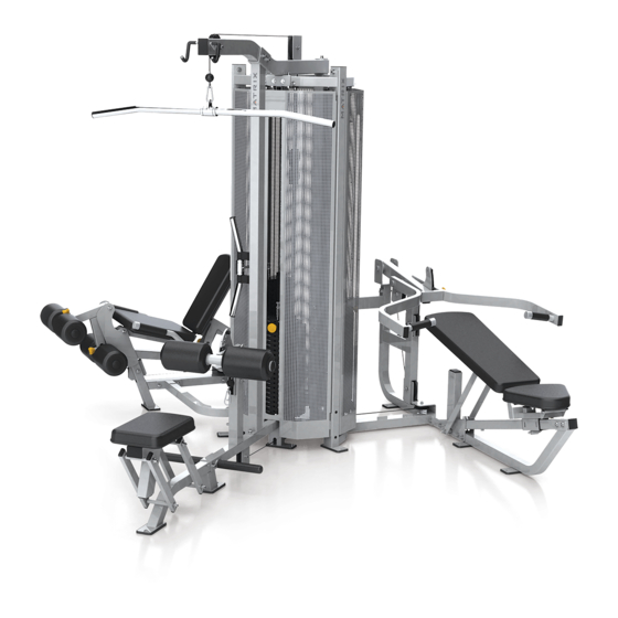
- Page 1 G1-GM30 3-STACK MULTI-GYM (GM167D) STRENGTH SERVICE MANUAL...
-
Page 2: Table Of Contents
TABLE OF CONTENTS CHAPTER 1: SERIAL NUMBER LOCATION …………………………..…… 3 CHAPTER 2: ASSEMBLY INSTRUCTIONS 2.1 G1MG30 3-Stack Multi-Gym Assembly Instructions..........4 CHAPTER 3: TROUBLESHOOTING ………………………………………………….….. …..13 Troubleshooting - Cable issue CHAPTER 4: PART REPLACEMENT INSTRUCTIONS 4.1 Hand Grip Foam Replacement................14 4.2 Seat Pad Replacement..................15 4.3 Back Pad Replacement..................17 4.4 Round Pad Replacement..................18 4.5 Seat Pad Adjustment Handle Replacement............20... -
Page 3: Chapter 1: Serial Number Location
CHAPTER 1: SERIAL NUMBER LOCATION 1.1 SERIAL NUMBER LOCATION The serial number is located at the bottom of the weight stack frame. -
Page 4: Chapter 2: Assembly Instructions
2.1 G1-MG30 3-STACK MULTI-GYM ASSEMBLY INSTRUCTIONS UNPACKING G1MG30 3-Stack Multi-Gym Thank you for purchasing a MATRIX Fitness product. This machine is an EN957-1 and EN957-2 complaint Class S product. Your MATRIX G1MG30 3-Stack Multi-Gym is inspected before it is packaged. It is shipped in multiple pieces to facilitate the compact packaging of the machine. - Page 5 THE STANDARD OF THE SCREW TORQUE Nom Diameter Torque (kg/cm) Torque (lbs/in) 1380 1197 2190 1901 3420 2968 4700 4079 2.1 G1-MG30 3-STACK MULTI-GYM ASSEMBLY INSTRUCTIONS - CONTINUED...
- Page 6 2.1 G1-MG30 3-STACK MULTI-GYM ASSEMBLY INSTRUCTIONS - CONTINUED...
- Page 7 2.1 G1-MG30 3-STACK MULTI-GYM ASSEMBLY INSTRUCTIONS - CONTINUED...
- Page 8 2.1 G1-MG30 3-STACK MULTI-GYM ASSEMBLY INSTRUCTIONS - CONTINUED...
- Page 9 2.1 G1-MG30 3-STACK MULTI-GYM ASSEMBLY INSTRUCTIONS - CONTINUED...
- Page 10 2.1 G1-MG30 3-STACK MULTI-GYM ASSEMBLY INSTRUCTIONS - CONTINUED...
- Page 11 2.1 G1-MG30 3-STACK MULTI-GYM ASSEMBLY INSTRUCTIONS - CONTINUED...
- Page 12 2.1 G1-MG30 3-STACK MULTI-GYM ASSEMBLY INSTRUCTIONS - CONTINUED...
-
Page 13: Chapter 3: Troubleshooting
CHAPTER 3: TROUBLESHOOTING 3.1 TROUBLESHOOTING – CABLE ISSUES CABLE IS LOOSE POSSIBLE CAUSES 1. The fix bolts are loosed. SOLUTION 1. Undo the former fixing nut , then the cable screw should be adjust fronted.(Figure A & B). 2. Lock the fixing nut (Figure C). Figure A Figure B Figure C... -
Page 14: Chapter 4: Part Replacement Instructions
CHAPTER 4: PART REPLACEMENT INSTRUCTIONS 4.1 HAND GRIP FOAM REPLACEMENT 1) To loose the screws of end cap of handlebar (Figure A). 2) To take off the end cap and cut off the original foam (Figure B). 3) Using tape to seal up the handlebar tube to avoid the oil or suds into the tube (Figure C). 4) To bent and hold the end of foam then put oil or suds into the inside of foam (Figure D). -
Page 15: Seat Pad Replacement
4.2 SEAT PAD REPLACEMENT 1) Use an 8MM L-Shaped Allen Wrench to take off 4 bolts from the old seat pad (Figure A) 2) Replace new pad and fix the 4 bolts (Figure B). Figure A Figure B 1) Use an 8MM L-Shaped Allen Wrench to take off 4 bolts from the old seat pad (Figure A) 2) Replace new pad and fix the 4 bolts ( Figure B) . - Page 16 1) Use an 8MM L-Shaped Allen Wrench to take off 4 bolts from the old seat pad (Figure A) 2) Replace new pad and fix the 4 bolts ( Figure B) . Figure A Figure B...
-
Page 17: Back Pad Replacement
4.3 BACK PAD REPLACEMENT 1) Use an 8MM L-Shaped Allen Wrench to take off 4 bolts from the old seat pad (Figure A) 2) Replace new pad and fix the 4 bolts ( Figure B) . Figure A Figure B 1) Use an 8MM L-Shaped Allen Wrench to take off 4 bolts from the old seat pad (Figure A) 2) Replace new pad and fix the 4 bolts ( Figure B) . -
Page 18: Round Pad Replacement
4.4 ROUND PAD ADJUSTMENT PIN REPLACEMENT 1) Remove the C ring with C ring pliers (Figure A). 2) Remove the round end cover and the round sleeve (Figure B). 3) Install the new round pad, and set the round end cover and round sleeve, then put the round pad onto the fixing tube (Figures C &... - Page 19 1) Use an 8MM L-Shaped Allen Wrench to take off bolts from the old seat pad (Figure A) 2) Take out the boltsand disc plastic interior. (Figure B). 3) Remove the old round pad. (Figure C). Replace the new round pad, then assemble the disc plastic interior and fix the bolt with L-Shaped Allen Wrench(Figure D) Figure A Figure B...
-
Page 20: Seat Pad Adjustment Handle Replacement
4.5 SEAT ADJUSTMENT HANDLE REPLACEMENT 1) Use a 24MM Open-Ended Wrench to take off the old adjustment pin set (Figure A). 2) Install a new adjustment pin (Figure B). Figure A Figure B 4.6 BACK ADJUSTMENT HANDLE REPLACEMENT 1) Use a 24MM Open-Ended Wrench to take off the old adjustment pin set (Figure A). 2) Install a new adjustment pin (Figure B). -
Page 21: Round Pad Adjustment Handle Replacement
4.7 ROUND ADJUSTMENT HANDLE REPLACEMENT 1) Using hand to take off the old adjustment pin set (Figure A). 2) Replace new adjustment pin and fix it (Figure B). Figure A Figure B 4.8 ARM ADJUSTMENT HANDLE REPLACEMENT 1) Use a 24MM Open-Ended Wrench to take off the old adjustment pin set (Figure A). 2) Install a new adjustment pin (Figure B). -
Page 22: Seat Sleeve Replacement
4.9 SEAT SLEEVE REPLACEMENT 1) Loose the screw (Figure A). 2) Tack out the seat (Figure B). 3) Take off the sleeve and then take off the tube bushing (Figure C). 4) Push the tube bushing into the sleeve ( Figure C).
Need help?
Do you have a question about the G1-GM30 and is the answer not in the manual?
Questions and answers