Table of Contents
Advertisement
Quick Links
Advertisement
Table of Contents

Subscribe to Our Youtube Channel
Related Manuals for Teltonika T-BoxN12R


Summary of Contents for Teltonika T-BoxN12R
- Page 1 TELTONIKA T-BoxN12R TBN-107 USER’S MANUAL V1.13...
-
Page 2: Table Of Contents
1. About this document..........................5 2. Introduction.............................. 6 3. Mechanical integration ..........................7 3.1. Package contents ..........................7 3.2. Dimensions ............................7 3.2.1. T-BoxN12R case........................7 3.2.2. Front panel ..........................8 3.2.3. Top view ............................ 8 4. Electrical integration..........................9 4.1. Electrical characteristics ........................9 4.1.1. - Page 3 10. Troubleshooting...........................20 10.1. T-BoxN12R doesn’t power up....................20 10.2. Nokia Configurator couldn’t connect to T-BoxN12R ............20 11. Technical specifications ........................23 11.1. Mechanical specifications and operating conditions...............23 11.2. Electrical parameters........................23 12. Technical support ..........................25...
- Page 4 Copyright © 2004 Teltonika. All rights reserved. Reproduction, transfer, distribution or storage of part or all of the contents in this document in any form without the prior written permission of Teltonika is prohibited. Nokia and Nokia Connecting People are registered trademarks of Nokia Corporation.
-
Page 5: About This Document
The document describes the mechanical, electrical, radio frequency (RF), antenna installation, PC software installation and configuration. Document also describes how to test and run T-BoxN12R for the first time. Note: Form more detail information integrator should be familiar with following documents: Nokia 12 Hardware Integrators Manual, Nokia M2M Platform Software Developer’s Guide, and Nokia 12... -
Page 6: Introduction
In AT mode it can be used as a wireless modem for PC to connect to the Internet. In I/O mode T-boxN12R can control external hardware by reading/writing I/O with a Java application or SMS. The functionality of T-BoxN12R can be expanded by connecting external hardware (controllers for Real-Time operation) to RS-232 interface. -
Page 7: Mechanical Integration
NOT be placed in metal case. The supplied antenna usually has 2 meter length cable, so if you plan to mount T-BoxN12R into a metal case, please mount the antenna outside the metal case. If cable length of 2 meters is not enough, contact our sales department (refer to page 25) to order antennas with longer cables. -
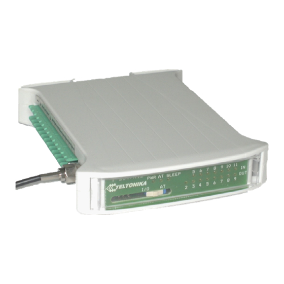
Page 8: Front Panel
3.2.2. Front panel Indication LEDs T-BOX/N12R PWR AT SLEEP 10 11 SIM card slot Switch I/O LEDs 3.2.3. Top view... -
Page 9: Electrical Integration
4. ELECTRICAL INTEGRATION 4.1. Electrical characteristics 4.1.1. Connector pin-out Table 1. Connector pin-out Pin name Description Device power. Voltage range from 9V to 30V DC. Power consumption: Stand by mode ~30mA@12V, peak up to 700mA@12V. As switched power regulator is used inside, the smaller the voltage, the bigger the current and vice versa (power consumption remains about the same) AIN3 Analog input 3. -
Page 10: Grounding
Table 2. Logical values for voltages of digital inputs Voltage Logical value 0 – 1 V 0 (False) 2 – 24 V 1 (True) Note: When T-BoxN12R operates in AT mode (switch is in position “AT”) outputs 2,3,4,5 and Inputs 5 and 6 are disabled! -
Page 11: Digital Outputs
4.2.2. Digital Outputs T-BoxN12R has open collector outputs. The picture below shows the internal circuit diagram of outputs implementation: Output Outputs can drive up to 70mA or 200mW load. The circuit has protection diode so outputs can directly drive relays. -
Page 12: Port1
I/O mode In AT mode outputs 2,3,4,5 and Inputs 5 and 6 are disabled! Note: After changing the position of the switch, please reboot T-BoxN12R (power off and on again) for the changes to take effect. The T-BoxN12R provides all signals for the industry standard DB9 RS-232C... -
Page 13: Port 2
Note: A special RJ45-DB9F cable is required in order to connect the device to the PC. The cable is supplied in the package. 4.3.2. PORT 2 Port 2 provides the second asynchronous channel with a simple handshaking capability (only RTS and CTS). The baud rate for Port 2 can be set to 9600, 19200, 38400, 57600 or 115200 bit/s. -
Page 14: Sample Electrical Connection
4.4. Sample electrical connection 4.4.1. Sample scheme... -
Page 15: Java (J2Me) Overview
5. JAVA (J2ME) OVERVIEW 5.1. Introduction Java technology enables writing applications to M2M devices in Java programming language. These Java applications can then be downloaded over-the-air to M2M devices for execution. This enables rapid application development and deployment. Traditionally, M2M application development for remote assets had to be done with C language. -
Page 16: M2M System Protocol Overview
6. M2M SYSTEM PROTOCOL OVERVIEW The Nokia 12 GSM module is part of the Nokia M2M Platform solution. The M2M system mode enables operating on the Nokia M2M Platform. The platform connects applications in a corporate intranet to the remote assets of the corporation utilising a selection of GSM bearers and Internet technology. -
Page 17: Introduction To Integrated Tcp/Ip Stack
7. INTRODUCTION TO INTEGRATED TCP/IP STACK In data communication, there is always need for low level communication protocols to ensure reliable data transmission. The protocol stacks are difficult and expensive to implement so the Nokia 12 GSM module provides in-build TCP/IP and UDP/IP transport layer protocol stacks. -
Page 18: Documents Provided By Nokia
8. DOCUMENTS PROVIDED BY NOKIA Nokia provides a full set of documents regarding M2M platform. Here is the list of most common and recommended document. Please be familiar with these documents before you start to integrate T-Box. • Nokia 12 Hardware Integration Manual •... -
Page 19: Software
9.2. Modem Drivers for Nokia 12 Modem drivers have to be installed when T-BoxN12R is used as a modem for PC. Note: When installing modem driver ensure that T-BoxN12R is connected to your PC. Modem has to be connected to the PC during the boot of the PC. Otherwise the OS will not find the modem. This issue is specific for particular operating systems (MS Windows XP, MS Windows 2000). -
Page 20: Troubleshooting
If the device powers up well, the “PWR” LED should be always on and output LEDs should be blinking one after another in a row. Note: the output LEDs are blinking, because a JAVA IMlet is pre-installed to your T-BoxN12R. If you load your own IMlet, it will not blink. - Page 21 Figure 4. New characters should appear instantly. If they do, the Figure 3. Hyper Terminal “Properties” selected COM port is the one, to window which T-BoxN12R is connected. If not, there is no connection and you should try the...
- Page 22 Please try to plug the cable to another PC COM port and change the settings in Nokia Configurator accordingly. Note: after plugging the cable to another COM port, please restart the T-BoxN12R. To do that you need to switch off the power, wait for at least 2-3 seconds and switch it on again.
-
Page 23: Technical Specifications
11. TECHNICAL SPECIFICATIONS 11.1. Mechanical specifications and operating conditions Parameter Typical Unit Size 120 x 101 x 22,55 Weight 148 ± 10 Operating temperature (absolute ºC maximum) Storage temperature ºC 11.2. Absolute maximum ratings Parameter Unit Maximum digital input voltage Maximum analog input voltage (DC) Maximum digital output voltage Maximum ratings are those values beyond which device damage can occur. - Page 24 OUT2, OUT3, OUT4, OUT5, OUT6, OUT7, OUT8, OUT9 IN5, IN6, IN7, IN8, IN9, IN10, IN11 AIN1, AIN2, AIN3...
-
Page 25: Technical Support
. We will be pleased to help you. If you are interested in other products from Teltonika, please visit our website www.teltonika.lt, where you will find our newest products. If you are interested in product pricing or want to order our products with different...
Need help?
Do you have a question about the T-BoxN12R and is the answer not in the manual?
Questions and answers