Table of Contents
Advertisement
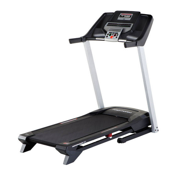
Model No. PETL59814.0
Serial No.
USER'S MANUAL
Write the serial number in the space
above for reference.
Serial Number
Decal
CUSTOMER SERVICE
UNITED KINGDOM
Call: 08457 089 009
From Ireland: 053 92 36102
Website: www.iconsupport.eu
E-mail: csuk@iconeurope.com
Write:
ICON Health & Fitness, Ltd.
Unit 1D, The Gateway
Fryers Way, Silkwood Park
OSSETT
WF5 9TJ
UNITED KINGDOM
AUSTRALIA
Call: 1800 993 770
E-mail: australiacc@iconfitness.com
Write:
ICON Health & Fitness
PO Box 635
WINSTON HILLS NSW 2153
AUSTRALIA
CAUTION
Read all precautions and instruc-
tions in this manual before using
this equipment. Keep this manual
for future reference.
www.iconeurope.com
Advertisement
Table of Contents

Related Manuals for Pro-Form 530 ZLT PETL59814.0


Summary of Contents for Pro-Form 530 ZLT PETL59814.0
- Page 1 Model No. PETL59814.0 Serial No. USER’S MANUAL Write the serial number in the space above for reference. Serial Number Decal CUSTOMER SERVICE UNITED KINGDOM Call: 08457 089 009 From Ireland: 053 92 36102 Website: www.iconsupport.eu E-mail: csuk@iconeurope.com Write: ICON Health & Fitness, Ltd. Unit 1D, The Gateway Fryers Way, Silkwood Park OSSETT...
-
Page 2: Table Of Contents
TABLE OF CONTENTS WARNING DECAL PLACEMENT ............. . .2 IMPORTANT PRECAUTIONS . -
Page 3: Important Precautions
IMPORTANT PRECAUTIONS WARNING: To reduce the risk of burns, fire, electric shock, or injury to persons, read all important precautions and instructions in this manual and all warnings on your treadmill before using your treadmill. ICON assumes no responsibility for personal injury or property damage sus- tained by or through the use of this product. - Page 4 DANGER: 21. Do not attempt to move the treadmill until Always unplug the power it is properly assembled. (See ASSEMBLY cord immediately after use, before clean- on page 7 and HOW TO FOLD AND MOVE ing the treadmill, and before performing the THE TREADMILL on page 21.) You must be maintenance and adjustment procedures able to safely lift 45 lbs.
-
Page 5: Before You Begin
BEFORE YOU BEGIN Thank you for selecting the new PROFORM 530 ZLT manual. To help us assist you, note the product model ® treadmill. The 530 ZLT treadmill provides an impressive number and serial number before contacting us. The selection of features designed to make your workouts model number and the location of the serial number at home more effective and enjoyable. -
Page 6: Part Identification Chart
PART IDENTIFICATION CHART Use the drawings below to identify small parts used for assembly. The number in parentheses below each draw- ing is the key number of the part, from the PART LIST near the end of this manual. The number following the key number is the quantity used for assembly. -
Page 7: Assembly
ASSEMBLY • Assembly requires two persons. • To identify small parts, see page 6. • Place all parts in a cleared area and remove the • Assembly requires the following tools: packing materials. Do not dispose of the packing the included hex key materials until you finish all assembly steps. - Page 8 2. Make sure that the power cord is unplugged. Remove and discard the two screws (A) and the shipping bracket (B) on the right side of the Base (74). Then, remove and discard the screws and the shipping bracket (not shown) on the left side of the Base.
- Page 9 4. Lay the Right Upright (76) near the Base (74) as shown. Attach the ground wire to the Base with a #8 x 1/2" Ground Screw (1). Then, press the Upright Grommet (73) into the square hole in the Right Upright (76). Ground Square Hole...
- Page 10 6. Identify the Right Handrail (64). Have a second person hold the Right Handrail near the Right Upright (76). Route the Upright Wire (63) into the bottom of the Right Handrail (64) and out of the hole in the Right Handrail. Be careful not to pinch the Upright Wire (63).
-
Page 11: Screws (8) And Four #10 Star Washers (23
8. Remove and discard the four indicated screws (C). 9. Attach the Console Crossbar (61) to the Left and Right Uprights (66, 76) with four #10 x 3/4" Screws (8) and four #10 Star Washers (23). Start all four Screws, and then tighten them. Then, firmly tighten the two 5/16"... - Page 12 10. With the help of a second person, hold the con- sole assembly near the Right Handrail (64). Console See the inset drawing. Connect the Upright Assembly Wire (63) to the console wire. The connectors should slide together easily and snap into place.
- Page 13 12. Raise the Frame (38) to the upright position. Have a second person hold the Frame until step 14 is completed. Orient the Latch Crossbar (67) as shown. Attach the Latch Crossbar to the brackets on the Frame (38) with two 1/4" x 1 3/4" Screws (77). Brackets 13.
- Page 14 14. Attach the upper end of the Storage Latch (68) to the bracket on the Latch Crossbar (67) with a 5/16" x 1 3/4" Bolt (79) and a 5/16" Nut (80). Lower the Frame (38) (see HOW TO LOWER THE TREADMILL FOR USE on page 21). 15.
-
Page 15: How To Use The Treadmill
HOW TO USE THE TREADMILL HOW TO PLUG IN THE POWER CORD Follow the steps below to plug in the power cord. This product must be earthed. If it should malfunc- 1. Plug the indicated end of the power cord into the tion or break down, earthing provides a path of least socket on the treadmill. - Page 16 CONSOLE DIAGRAM FEATURES OF THE CONSOLE To turn on the power, see page 17. To use the man- ual mode, see page 17. To use a preset workout, see page 19. To use the information mode, see page 20. The treadmill console offers a selection of features To use the sound system, see page 20.
-
Page 17: To Turn On Power
HOW TO TURN ON THE POWER HOW TO USE THE MANUAL MODE IMPORTANT: If the treadmill has been exposed to 1. Insert the key into the console. cold temperatures, allow it to warm to room tem- perature before you turn on the power. If you do See HOW TO TURN ON THE POWER at the left. - Page 18 4. Change the incline of the treadmill as desired. burned during your workout. The display will also show your heart rate when you use the handgrip To change the incline of the treadmill, press the heart rate monitor (see step 6). Incline increase and decrease buttons or one of the Quick Incline buttons.
- Page 19 7. Turn on the fan if desired. 3. Start the walking belt. The fan features two speed Press the Start button or the Speed increase but- settings. Press the fan button ton to start the workout. A moment after you press repeatedly to select High or Low the button, the treadmill will automatically adjust to or to turn off the fan.
-
Page 20: Information Mode
To stop the workout at any time, press the Stop The lower left display will show the total number of kilo- button. To restart the workout, press the Start but- meters or miles that the walking belt has moved. ton or the Speed increase button. The walking belt will begin to move at 2 Km/H. -
Page 21: How To Fold And Move The Treadmill
HOW TO FOLD AND MOVE THE TREADMILL HOW TO FOLD THE TREADMILL HOW TO MOVE THE TREADMILL To avoid damaging the treadmill, adjust the incline Before moving the treadmill, fold it as described at the to zero before you fold the treadmill. Then, remove left. -
Page 22: Maintenance And Troubleshooting
MAINTENANCE AND TROUBLESHOOTING MAINTENANCE b. Make sure that the power cord is plugged in. If the power cord is plugged in, unplug it, wait for five Regularly clean the treadmill and keep the walking belt minutes, and then plug it back in. clean and dry. - Page 23 Locate the Reed Switch (85) and the Magnet (86) b. If the walking belt is overtightened, treadmill per- on the right side of the Pulley (31). Turn the Pulley formance may decrease and the walking belt may until the Magnet is aligned with the Reed Switch. become damaged.
- Page 24 SYMPTOM: The walking belt is off-center SYMPTOM: The walking belt slips when walked on IMPORTANT: The walking belt should be centered a. First, remove the key and UNPLUG THE POWER between the foot rails. If the walking belt rubs CORD. Using the hex key, turn both idler roller against the foot rails, the walking belt may become screws clockwise, 1/4 of a turn.
-
Page 25: Exercise Guidelines
EXERCISE GUIDELINES Burning Fat—To burn fat effectively, you must exer- WARNING: cise at a low intensity level for a sustained period of Before beginning this time. During the first few minutes of exercise, your or any exercise program, consult your physi- body uses carbohydrate calories for energy. - Page 26 SUGGESTED STRETCHES The correct form for several basic stretches is shown at the right. Move slowly as you stretch —never bounce. 1. Toe Touch Stretch Stand with your knees bent slightly and slowly bend forward from your hips. Allow your back and shoulders to relax as you reach down toward your toes as far as possible.
- Page 27 NOTES...
-
Page 28: Part List
PART LIST Model No. PETL59814.0 R0414A Key No. Qty. Description Key No. Qty. Description #8 x 1/2" Ground Screw Drive Motor Belt 3/8" x 3 1/4" Screw Right Rear Foot 3/8" Star Washer #10 Flat Washer #8 x 3/4" Screw Motor Hood 5/16"... -
Page 29: Exploded Drawing
EXPLODED DRAWING A Model No. PETL59814.0 R0414A... - Page 30 EXPLODED DRAWING B Model No. PETL59814.0 R0414A...
- Page 31 EXPLODED DRAWING C Model No. PETL59814.0 R0414A...
-
Page 32: Ordering Replacement Parts
ORDERING REPLACEMENT PARTS To order replacement parts, please see the front cover of this manual. To help us assist you, be prepared to provide the following information when contacting us: • the model number and serial number of the product (see the front cover of this manual) •...
Need help?
Do you have a question about the 530 ZLT PETL59814.0 and is the answer not in the manual?
Questions and answers