Table of Contents
Advertisement
Advertisement
Table of Contents

Related Manuals for Heatmiser smartstat


Summary of Contents for Heatmiser smartstat
- Page 2 Model: Available in : Sapphire Black and Glacier White...
-
Page 3: Table Of Contents
Re-calibrating the Thermostat Re-calibrating the Thermostat WiFi Setup - Automatic WiFi Setup 9-10 Error Codes Error Codes WiFi Setup - Manual Pairing with SmartStat App 11-12 29-31 Profiles Thermostat Mode Wiring Diagram Pairing with the SmartApp 33-35 Thermostat Mode Wiring Diagram... -
Page 4: What Is A Programmable Room Thermostat
What is a Programmable Room Thermostat? What is a Programmable Room Thermostat? A programmable room thermostat is both a programmer and a room thermostat. A programmable room thermostat is both a programmer and a room thermostat. A programmer allows you to set “On” and “Off” periods to suit your own lifestyle. A programmer allows you to set “On”... - Page 5 The way to set and use your programmable room thermostat is to find the lowest The way to set and use your programmable room thermostat is to find the lowest temperature settings that you are comfortable with at the different times you have temperature settings that you are comfortable with at the different times you have chosen, and then leave it alone to do its job.
-
Page 6: Installation Procedure
Screw the SmartStat back plate securely into the back box. Step 4 Step 4 Clip the front of the SmartStat onto the back plate, securing it in place with the Clip the front of the SmartStat onto the back plate, securing it in place with the retaining screw. -
Page 8: Mode Select / Factory Reset
Mode Select / Factory Reset Mode Select This SmartStat can either be used as a thermostat or a time clock. This SmartStat can either be used as a thermostat or a time clock. Thermostat mode is the default setting. Thermostat mode is the default setting. - Page 9 Thermostat mode Mode Select Time Clock Mode Restart Screen Thermostat mode Mode Select Time Clock Mode Restart Screen...
-
Page 10: Wifi Setup - Automatic Wifi Setup
• Press the Tick key to confirm ..................The SmartStat will then connect to the chosen WiFi network. During this process the WiFi The SmartStat will attempt to connect to the network. icon and “Connecting” will be displayed. If successful a Tick symbol will be displayed next to the network name, the SmartStat will then return to the main display. - Page 11 1. WiFi Setup Menu 2. List of Networks ‘Add Zone' • On the SmartStat, use the Left / Right keys to scroll to setup and press Tick ....................... • ‘Pairing with App’ will be highlighted in the menu, press the Tick key to start pairing ......................
-
Page 12: Mode 1 - Thermostat
Mode 1 - Thermostat WiFi Setup - Manual To connect the SmartStat with the WiFi network follow these steps. • Use the Left / Right keys to scroll to Setup and press Tick ....• Use the Up/Down keys to scroll to WiFi Setup and press Tick ..... - Page 13 The SmartStat will attempt to connect to the network. During this process the WiFi icon and “Attempting to Connect” will be displayed. If successful a Tick will be displayed next to the network name. 1. WiFi Manual Setup Menu 2. SSID Name Entry 3.
- Page 14 Holiday – Displayed when the thermostat is in holiday mode. • On the SmartStat, use the Left / Right keys to scroll to setup and press Tick ...................... Floor Limit Symbol – Displayed when the floor probe has reached the floor •...
- Page 15 Room Temperature Floor Temperature When the SmartStat is set to use both the air & the floor sensor, the room temperature will be displayed by default. To view the current floor temperature, press and hold the Left and Right arrow...
-
Page 16: Setting The Time And Date
Setting the Time and Date Note: When the SmartStat is paired with the app, the time & date settings are automatically synchronised according to the location’s time zone setting. To set the clock, follow these steps. • Use the Left / Right keys to scroll to Clock ............ -
Page 17: Comfort Levels Explained
You also have the option to use the SmartStat in Non-Programmable mode. Temperature Format – Degrees Celsius or Fahrenheit. The SmartStat is supplied with comfort levels already programmed, but these can be WiFi Indicator - Displayed when connected to a WiFi network. -
Page 18: Temperature Display
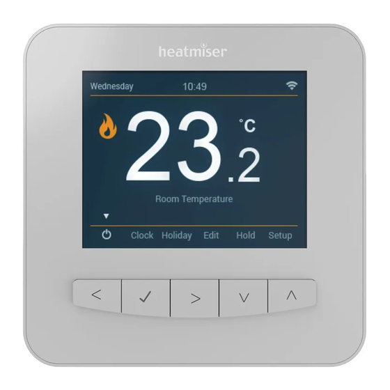
Floor Temperature Set Temperature When the SmartStat is set to use both the air & the floor sensor, the room temperature will be displayed by default. To view the current floor temperature, press and hold the Left and Right arrow keys for 5 seconds, the floor temperature will then be displayed. -
Page 19: Temperature Control
Temperature Control Setting the Time and Date The Up / Down keys allow you to adjust the current set temperature .... To set the clock, follow these steps. When you press either of these keys, you will see the Set Temperature and •... -
Page 20: Temperature Hold
• Use the Left / Right keys to scroll to Hold and press Tick ....... The SmartStat is supplied with comfort levels already programmed, but these can be • Use the Up / Down keys to set the desired Hold time ........ -
Page 21: Locking/Unlocking The Smartstat
Note: The keypad lock indicator is only displayed when the lock is active. Unlocking the SmartStat Program Mode Set Time To unlock the SmartStat press Tick once. The display will show **** and you will need to enter the four digit pin number you set previously. Set Temperature •... - Page 22 The Frost Protection Symbol will toggle ON/OFF each time Tick is pressed ....the desired temperature value. In this mode, the SmartStat will only turn the heating ON should the room temperature Use the Up / Down keys to adjust the set value ............
- Page 23 • Use the Up / Down keys to set the desired Hold time ........To turn the SmartStat off completely, scroll to the Power Icon and hold the Tick key for approximately 4 seconds until the display goes blank ....
- Page 24 To cancel the holiday, repeat these steps but reduce the Holiday duration to 00 days. To unlock the SmartStat press Tick once. The display will show **** and you will need to Note: A holiday period does not start until 00:00 the next day. For example, if you set a enter the four digit pin number you set previously.
-
Page 25: Optional Features Explained
The Away symbol will toggle ON/OFF each time Tick is pressed ........Pairing With the App: This function is used to pair the SmartStat to the SmartStat App. In this mode, the SmartStat will only turn the heating ON should the room temperature WiFi Set-Up: This function is used to connect the SmartStat with the WiFi network. -
Page 26: Power On/Off
1°C (with The display and heating output will be turned OFF. a rate of change of 20, the SmartStat has calculated the heating needs 20 minutes to raise the building temperature 1°C) and starts the heating accordingly. -
Page 27: Adjusting The Optional Settings
In thermostat mode; the holiday function reduces the set temperature in your home to the Away mode temperature setting that is configured in the setup menu. The SmartStat will maintain this temperature for the duration of the holiday and will then automatically return to the program mode on your return. -
Page 28: Optional Features
NEED NOT BE ADJUSTED. Used to add pair with the SmartStat App Pairing with App Pairing With the App: This function is used to pair the SmartStat to the SmartStat App. WiFi Setup Used to connect to the WiFi network WiFi Set-Up: This function is used to connect the SmartStat with the WiFi network. -
Page 29: Error Codes
1°C (with • The current temperature will appear on the display. a rate of change of 20, the SmartStat has calculated the heating needs 20 minutes to • Use the Up / Down keys to configure the new temperature value ..... - Page 30 Wiring Diagram – Volt Free Output Adjusting the Optional Settings • Use the Left / Right keys to select Setup ............• Press Tick to confirm selection ................... TIMER RT2 RT1 Feature Editing Features Menu Neutral 230V Supply In Live •...
- Page 31 Wiring Diagram – Switch Live Output Optional Settings - Feature Table FEATURE SETTING Used to add pair with the SmartStat App Pairing with App WiFi Setup Used to connect to the WiFi network Switching Differential - 3.0 C (0.5 C = Default)
- Page 32 Wiring Diagram - Switch Live to UH3 Re-calibrating the SmartStat If you need to re-calibrate the SmartStat, follow these steps. • Use the Left / Right keys to scroll to the Power Icon ........• Press and hold Tick to turn the display OFF ..............
-
Page 33: Mode 2 - Time Clock
Mode 2 - Time Clock Profiles Using the SmartStat App, you can create up to four profiles. Profiles are stored comfort levels that you can easily access and send to your thermostat as and when you need them. For example, if you work different shift patterns from week to week, you could have... - Page 34 Wiring Diagram - Volt Free to Boiler TIMER Neutral 230V Supply In Live Volt Free To Boiler This product must only be installed by a qualified electrician and comply with local installation regulations.
- Page 35 Wiring Diagram - Switch Live LCD Display Day Indicator - Displays the day of the week. Away – Displayed when Away mode is active. Clock - Time displayed in 24 hour format. Holiday – Displayed when the time clock is in Holiday mode. Timer Status –...
- Page 36 Wiring Diagram - Switch Live to UH3 Setting the Switching Times To program the switching times, follow these steps • Use the Left / Right keys to scroll to Edit ..............• Press Tick to confirm selection ....................• Use the Up/Down keys to select the day/period to program ......TIMER •...
- Page 37 Timer Boost Mode 2 - Time Clock To boost the timed output ON follow these steps. • Use the Left / Right keys to scroll to Boost and press Tick ..... • Use the Up / Down keys to set the hours ............... •...
- Page 38 Optional Features Explained Pairing With the App: This function is used to pair the SmartStat to the SmartStat App. WiFi Set-Up: This function is used to connect the SmartStat with the WiFi network. Program Mode: The time clock offers three programming modes: Weekday/Weekend (5/2), 7 Day Programming or 24 Hour.
- Page 39 Wiring Diagram - Time Clock Mode LCD Display (Mid Position Valve) Day Indicator - Displays the day of the week. Away – Displayed when Away mode is active. Clock - Time displayed in 24 hour format. Holiday – Displayed when the time clock is in Holiday mode. TIMER Timer Status –...
-
Page 40: Setting The Switching Times
Wiring Diagram - Time Clock Mode Setting the Switching Times (S Plan) To program the switching times, follow these steps • Use the Left / Right keys to scroll to Edit ..............• Press Tick to confirm selection ....................• Use the Up/Down keys to select the day/period to program ...... -
Page 41: Timer Boost
Notes Timer Boost To boost the timed output ON follow these steps..................................• Use the Left / Right keys to scroll to Boost and press Tick ....................................... • Use the Up / Down keys to set the hours ............... •... -
Page 42: Optional Features
Notes Optional Features Explained Pairing With the App: This function is used to pair the SmartStat to the SmartStat App. WiFi Set-Up: This function is used to connect the SmartStat with the WiFi network..................................Program Mode: The time clock offers three programming modes: .................................. - Page 43 Notes Wiring Diagram - Time Clock Mode (Mid Position Valve) ......................................................................................................TIMER ......................................................................................................Neutral Mid Position ..................................Valve 230V Supply In Hot Water Stat Live ..................................To Heating On Boiler Enable ........................................................................................................................................This product must only be installed by a qualified electrician ..................................
- Page 44 Want More Information? Call our support team on: +44 (0)1254 669090 www.heatmiser.com Facebook: facebook.com/thermostats Twitter: @heatmiseruk Rev 1.0...
Need help?
Do you have a question about the smartstat and is the answer not in the manual?
Questions and answers