Table of Contents
Advertisement
Quick Links
FDM-FSK
Fiber Optic Modem
With
Built in Model 4xx Series
FSK Modem
USER GUIDE
FDM Series
All Fiber Topologies - Compliant
(TI) 16 August 2006
GDI COMMUNICATIONS LLC
PO Box 1330
280 I-80 Exit 1
Verdi, NV 89439
Phone: (775) 345-8000
Fax:
(775) 345-8010
Email: support@sgdi.com
16 Aug 06 FDM-FSK Preliminary User Guide
Dwg: A01230
Advertisement
Table of Contents

Related Manuals for GDI FDM-FSK

Summary of Contents for GDI FDM-FSK
- Page 1 FDM Series All Fiber Topologies - Compliant (TI) 16 August 2006 GDI COMMUNICATIONS LLC PO Box 1330 280 I-80 Exit 1 Verdi, NV 89439 Phone: (775) 345-8000 Fax: (775) 345-8010 Email: support@sgdi.com 16 Aug 06 FDM-FSK Preliminary User Guide Dwg: A01230...
-
Page 2: Fdm-Fsk
Necessary for Remote Fiber to 2/4Wire FSK to TMC applications. • Auxiliary Data Port For 2/4Wire FSK or SS Radio Branch Circuits. • Built-in Uninterruptible Power Supply Provides Optical Continuity at a Failed Intersection. 16 Aug 06 FDM-FSK Preliminary User Guide Dwg: A01230... -
Page 3: Table Of Contents
2/4 Wire LED Displays Carrier Detect Key On Data Request To Send Clear To Send Transmit Data Receive Data DC Power Center Display DC Power Center LED Indicators Main Charging Battery Alarm 16 August 06 FDM-FSK Preliminary User Guide Dwg: A01230... - Page 4 Fiber Identification Techniques Fiber Applications Self Healing Dual Counter Rotating Ring Operation Single Ring Operation Point to Point Point to Point with Redundant Fiber Path Daisy Chain Operation Dual Daisy Chain (Center Master) 16 August 06 FDM-FSK Preliminary User Guide Dwg: A01230...
- Page 5 Copper to Fiber to Copper --- Fiber Bridge Application Fiber with Copper Branch --- Copper Tap Application Factory Default Settings and Pin-Out Diagrams KOD Jumper Care and Handling Procedures for Optical Connectors Disclaimer 16 August 06 FDM-FSK Preliminary User Guide Dwg: A01230...
-
Page 6: Fdm Series Overview
4. The FDM FiberHub performs as a 1 x 3 star optical hub that ties in optical branch circuits into the mainstream communications path. 5. The FDM-FSK is a combination of a FDM2SA and a FSK modem. 6. The FDM-SSR is a combination of a FDM2SA and a Spread Spectrum Radio. -
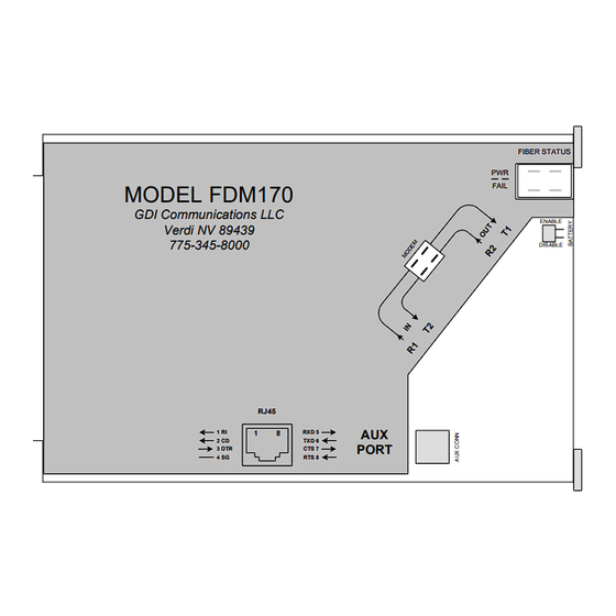
Page 7: Fdm170
2070’s spare Serial Ports SP2 or SP4 (slot dependant) is also brought out to the front panel. For rack-mounted communications at the Traffic Maintenance Center, R400/R800 Series Racks would be populated with the FDM170 to complete the communications system. 16 August 06 FDM-FSK Preliminary User Guide Dwg: A01230... -
Page 8: Fdm-Fiberhub
This unique feature allows a Remote Fiber System (Tail Circuit) to be integrated into a 4wire FSK circuit and on to city hall. FDM-FSK This user guide describes the FDM-FSK and its operation. 16 August 06 FDM-FSK Preliminary User Guide Dwg: A01230... -
Page 9: Introduction To The Fdm-Fsk Modem
INTRODUCTION to the FDM-FSK FDM-FSK The FDM-FSK is a combination of the FDM2SA FDM-FSK Modem Fiber Optic Modem and GDI’s Model 4xx Series FSK Modem, basically it is two interconnected FDM2SA Fiber Trunk Fiber Optic Fiber Trunk modems housed in the same enclosure. Two RS232... -
Page 10: Modem Ergonomics
The FSK Port can operate in 2 or 4 wire mode (Half/ Full Duplex) and is 100% compatible with all GDI FSK Modems The FDM-FSK has three mounting options, left or right wall mounting via a pair of “Keyhole” slots on both sides, or as a Stand Alone shelf mounted unit while still maintaining a vertical front panel view for all three options. -
Page 11: Fiber Optic Modem Displays
1or 2 to denote which receiver that fiber belongs to. See Installation Section -- Fiber Identification Techniques, page 22 for more details. Display indicates patchcord belongs in R2. Display indicates patchcord belongs in R1. 16 August 06 FDM-FSK Preliminary User Guide Dwg: A01230... -
Page 12: Fiber Status Displays For Redundant Rings And Daisy Chains
Fiber Status Display for Single Rings Loss of signal on R1 Master Displays will Flash Master Slave 1 Displays will Flash Master Slave 1 Slave 2 Master Slave 1 Slave 2 16 August 06 FDM-FSK Preliminary User Guide Dwg: A01230... -
Page 13: 2/4 Wire Led Displays
Running on Battery Power with If the installation site supports a 24VDC UPS this may be an Alarm indication. connected to the DC power connector on the modem in lieu of an internal UPS. 16 August 06 FDM-FSK Preliminary User Guide Dwg: A01230... -
Page 14: Dc Power Center Led Indicators
4W FSK The modem can be connected to an external 24VDC UPS via the DC Jack, also a battery disconnect switch is provided for shipping or storage purposes. Battery 18-30VDC Enable Disable 16 August 06 FDM-FSK Preliminary User Guide Dwg: A01230... -
Page 15: Dual Data Ports
Bottom Panel Port Switch Assignment Switch Actuator This panel is where the FDM-FSK is set up for Fiber and FSK Full Half Duplex Duplex Operation. -
Page 16: Signal Flow Diagrams
• Response Data entering the Remotes Main, Auxiliary and FSK Ports is transmitted back to the Master Modem. • At the Master Modem, Response Data from the Remotes is passed to the Masters Main and Auxiliary Ports and back to the Servers. 16 August 06 FDM-FSK Preliminary User Guide Dwg: A01230... -
Page 17: Data Port Flow Diagrams
“Keyhole” slots. Both sides have pairs of keyhole slots for left or right wall mounting so as to maintain the desired front or rear panel view, hole centers are at 7.5inches. 16 August 06 FDM-FSK Preliminary User Guide Dwg: A01230... -
Page 18: Setting Up The Modem
• Carrier Turn Off Time • Local Echo • Receiver Squelch Time • Carrier Detect • Load Compensation It is suggested that you first configure the FDM Modem and then configure the FSK Modem. 16 August 06 FDM-FSK Preliminary User Guide Dwg: A01230... -
Page 19: Fdm Dip Switches
Single Ring 3. Daisy Chain 2 Rings 1 Ring This selection is for the classic Daisy Chain, leave the Daisy Chain Ring previous switch set to 2 Rings. 16 August 06 FDM-FSK Preliminary User Guide Dwg: A01230... -
Page 20: Data Protocol Rs232/422
CTS-0ms The RTS to CTS delay can be set at 0ms or 8ms, 0ms is for fast operation and 8 ms is used for external transmission systems that require a delay. 16 August 06 FDM-FSK Preliminary User Guide Dwg: A01230... -
Page 21: Anti-Streaming
If the front panel anti- streaming RESET switch is momentary pushed, the system will automatically reset and the alarm LED will extinguish. Auxiliary Port DCE/DTE Options The FDM-FSK is primarily designed for Slave applications, therefore this selection is left in the DCE mode. Aux.Port DCE... -
Page 22: Fiber Identification Techniques
Note: City Hall will also have the Daisy Chain Display, if it was set to 2 Rings then it will have a Fold-Back display. Master Slave 1 4. Continue steps 2 and 3 until you reach the end of the Daisy Chain. 16 August 06 FDM-FSK Preliminary User Guide Dwg: A01230... -
Page 23: Fiber Applications
Master Modem Slave Modem Master Slave 2 Rings 2 Rings RS232 RS232 9600 9600 None (Parity) None (Parity) RTS/CTS RTS/CTS CTS-0ms CTS-0ms Anti-Stream 2 Seconds Aux Port Normal Aux Port Modem 16 August 06 FDM-FSK Preliminary User Guide Dwg: A01230... - Page 24 The above diagram shows a catastrophic event at Slave 2, with the resulting graphics displays below. Slave 3 Slave 1 Master Indicates “Fiber Communications” Fold-Back indication Fold-Back indication are good in this segment. 16 August 06 FDM-FSK Preliminary User Guide Dwg: A01230...
-
Page 25: Single Ring Operation
Off position or “other selection”. Master Modem Slave Modem Master Slave 1 Ring 1 Ring RS232 RS232 9600 9600 None None RTS/CTS RTS/CTS CTS-0ms CTS-0ms Anti-Stream 2 Seconds Aux Port Normal Aux Port Normal 16 August 06 FDM-FSK Preliminary User Guide Dwg: A01230... - Page 26 Loss Of Signal alarm (LOS) The following displays indicate a progressive build out of a Single Ring. Master Master Slave 1 Master Slave 1 Slave 2 Master Slave 1 Slave 2 16 August 06 FDM-FSK Preliminary User Guide Dwg: A01230...
-
Page 27: Point To Point
Off position or “other selection”. Master Modem Slave Modem Master Slave 1 Ring 1 Ring RS232 RS232 9600 9600 None None RTS/CTS RTS/CTS CTS-0ms CTS-0ms Anti-Stream 2 Seconds Aux Port Normal Aux Port Normal 16 August 06 FDM-FSK Preliminary User Guide Dwg: A01230... -
Page 28: Point To Point With Redundant Fiber Path
Off position or “other selection”. Master Modem Slave Modem Master Slave 2 Ring 2 Ring RS232 RS232 9600 9600 None None RTS/CTS RTS/CTS CTS-0ms CTS-0ms Anti-Stream 2 Seconds Aux Port Normal Aux Port Normal 16 August 06 FDM-FSK Preliminary User Guide Dwg: A01230... - Page 29 Status Display Fiber Status Fiber Status Normal Normal A failure of any receive fiber would cause the following fold-back indication to be displayed. 16 August 06 FDM-FSK Preliminary User Guide Dwg: A01230...
-
Page 30: Daisy Chain Operation
None RTS/CTS RTS/CTS RTS/CTS RTS/CTS CTS-0ms CTS-0ms CTS-0ms CTS-0ms Anti-Stream Anti-Stream Anti-Stream N.A. 2 Seconds 2 Seconds 2 Seconds Aux Port Normal Aux Port Normal Aux Port Normal Aux Port Normal 16 August 06 FDM-FSK Preliminary User Guide Dwg: A01230... -
Page 31: Status Display
The down-stream isolated modems are in communications with each other and will automatically come back on line when the break is repaired. 16 August 06 FDM-FSK Preliminary User Guide Dwg: A01230... -
Page 32: Dual Daisy Chain (Center Master)
RTS/CTS RTS/CTS RTS/CTS CTS-0ms CTS-0ms CTS-0ms CTS-0ms Anti-Stream Anti-Stream Anti-Stream 2 Seconds 2 Seconds 2 Seconds C-Mast 64 * Aux Port Normal Aux Port Normal Aux Port Normal Aux Port Normal 16 August 06 FDM-FSK Preliminary User Guide Dwg: A01230... -
Page 33: Configuring The Fsk Modem Section
The rate at which the communication line changes state is known as the baud rate, this can be interpreted to be equivalent of bits per second. The 4xx Series of Modems are capable of communicating at baud rates up to 19200Kbts depending on the model. 16 August 06 FDM-FSK Preliminary User Guide Dwg: A01230... -
Page 34: Communications Sequence Of Events
This action “closes the modems door” to prevent noisy lines from false triggering the data circuits. The modem is now quiet. 5. We have now completed the Polling phase. 16 August 06 FDM-FSK Preliminary User Guide Dwg: A01230... -
Page 35: The Response
This action “closes the modems door” to prevent noisy lines from false triggering the data circuits. The modem is now quiet. 7. We have now completed the Response phase. 16 August 06 FDM-FSK Preliminary User Guide Dwg: A01230... -
Page 36: Front, Rear And Bottom Panels
“copper”. The modem can operate 4W FSK in either 2 wire or 4 wire duplex modes. Note that in 2 wire operation the cable pair is connected to the “OUT” terminals on all modems. 16 August 06 FDM-FSK Preliminary User Guide Dwg: A01230... -
Page 37: Bottom Panel Dip Switches
Normally this is set to 600 Ohm to match the line impedance. Switching to High increases the gain of the receiver and is only used when the receive signal is so low it causes data errors. 16 August 06 FDM-FSK Preliminary User Guide Dwg: A01230... -
Page 38: Fsk Applications
The remote modems have to wait until the FDM-FSK modem has stopped transmitting before it can send a message back; therefore it is important to slow things down by setting the modems timing parameters to the longest times. -
Page 39: Full Duplex Operation (4 Wire "2 Pairs")
The Poll AUDIO OUT from the FDM-FSK connects to the Local’s AUDIO IN. The Response AUDIO OUT from the Locals connects to the FDM-FSK AUDIO IN. -
Page 40: A Word On Dynamic Range
Before installing any modem make sure that the cable pairs have Lightning Protectors installed at each modem location, please make sure that the protective device is grounded according to National Electrical Code. 16 August 06 FDM-FSK Preliminary User Guide Dwg: A01230... - Page 41 Dual Counter Rotating Ring Series Series SSRadio Local FDM Series 2 / 4 Wire FSK RS232 Controller Series FDM2SA FDM170 FDM2070 Local FDM-FSK Controller FDM-SSR South Arterial Daisy Chain FDM-FiberHub Local RS232 Controller Series 16 August 06 FDM-FSK Preliminary User Guide Dwg: A01230...
-
Page 42: Fiber To Copper To Fiber --- Copper Bridge Application
2 or 4 2 or 4 FDM-SSR wire wire FDM-FiberHub Series Series Slave Modem Modem Master Slave Slave Slave Note the Master is at the start of the new fiber system 16 August 06 FDM-FSK Preliminary User Guide Dwg: A01230... -
Page 43: Fiber With Copper Branch --- Copper Tap Application
Modem 2 or 4 wire In this application the FDM-FSK is the “head-end or master” for the fiber to copper communications. The control of the FSK by the FDM can be set to operate according to your particular system requirements. -
Page 44: Factory Default Settings
7 CTS 5 RXD 8 RTS CTS RTS NO CONNECTION NO CONNECTION PINS 4-6-9 PINS 1-3 Pins Main Port DCE Data Flows Auxiliary Port DCE Data Flows DCD (KOD RTS) Common Common 16 August 06 FDM-FSK Preliminary User Guide Dwg: A01230... -
Page 45: Kod Jumper
2. It can assert DCD dynamically before data, then de-assert DCD after data; this is used to handshake the built-in FSK modem. Use at a 2W Master or 2 or 4W Slave location. 16 August 06 FDM-FSK Preliminary User Guide Dwg: A01230... -
Page 46: Care And Handling Procedures For Optical Connectors
There are several versions of this device readily available from supply houses. Note: This only polishes the end surface and does not clean the ferrules cylindrical surface that contributes to axial alignment. 16 August 06 FDM-FSK Preliminary User Guide Dwg: A01230... - Page 47 Air Duster, this will reduce the possibility of dust contaminating the optical connector as well as the optical receptacle. Do not re-use a tissue, discard it. 16 August 06 FDM-FSK Preliminary User Guide Dwg: A01230...
- Page 48 7. Insert the ferrule into the receptacle and slowly rotate the connector until the key aligns itself with the receptacles keyway, then push the connector home and engage the connectors locking mechanism. Do not force the connector; it should be a snug fit. 16 August 06 FDM-FSK Preliminary User Guide Dwg: A01230...
- Page 49 Contents of this user guide may not be copied or published without the written consent of GDI Communications LLC, Verdi, Nevada. The contents of this user guide are deemed to be correct at the time of publishing and are offered as a guide only; GDI Communications LLC is not liable for any inaccuracies or omissions.
Need help?
Do you have a question about the FDM-FSK and is the answer not in the manual?
Questions and answers