Table of Contents
Advertisement
4 Burner Gas Grill
OWNER'S MANUAL MODEL 810-3420-A
ASSEMBLY AND OPERATING IN STRUC TIONS
SAVE THIS MANUAL FOR FUTURE REFERENCE
WARNING
FOR YOUR SAFETY
If you smell gas:
1. Shut off gas to the appliance.
2. Extinguish any open flame.
3. Open barbecue lid or hood.
4. If odour continues, discontinue use
and contact your local dealer.
• Use outdoors only.
• Read instructions before using the appliance. Failure to follow instructions
could result in death, serious bodily injury, and/or property loss.
• Warning: accessible parts may be very hot. Keep young children away.
• Do not move the appliance during use.
• Turn off the gas supply at the gas cylinder after use.
• Any modification of the appliance, misuse, or failure to follow the
instructions may be dangerous and will invalidate your warranty. This does
not affect your statutory rights.
• Retain these instructions for future reference.
• Leak test your barbecue annually. Check the hose connections are tight
and leak test them each time you reconnect the gas bottle.
FOR YOUR SAFETY
1. Do not store or use petrol or other
flammable vapours or liquids in the
vicinity of this or any other appliance.
2. A gas cylinder not connected for use
shall not be stored in the vicinity of
this or any other appliance
Advertisement
Table of Contents

Related Manuals for Brinkmann 810-3420-A


Summary of Contents for Brinkmann 810-3420-A
- Page 1 4 Burner Gas Grill OWNER’S MANUAL MODEL 810-3420-A ASSEMBLY AND OPERATING IN STRUC TIONS SAVE THIS MANUAL FOR FUTURE REFERENCE • Use outdoors only. • Read instructions before using the appliance. Failure to follow instructions could result in death, serious bodily injury, and/or property loss.
- Page 2 Manufacturer The Brinkmann Corporation 0359-14 Product Name Outdoor Gas Grill Appliance 0359CO1318 Model Number 810-3420-A 16B.02.14.039 3+(28-30/37) BE, CH, CY, CZ, ES, FR, GB, GR, IE, IT, LT, LU, LV, PT, SK, SI Country of Great Britain (GB) Destination Gas Type and...
- Page 3 IMPORTANT SAFETY WARNINGS WE WANT YOU TO ASSEMBLE AND USE YOUR GRILL AS SAFELY AS POSSIBLE. THE PURPOSE OF THIS SAFETY ALERT SYMBOL IS TO ATTRACT YOUR ATTENTION TO POSSIBLE HAZARDS AS YOU ASSEMBLE AND USE YOUR GRILL. WHEN YOU SEE THE SAFETY ALERT SYMBOL PAY CLOSE ATTENTION TO THE INFORMATION WHICH FOLLOWS! READ ALL SAFETY WARNINGS AND INSTRUCTIONS CAREFULLY BEFORE ASSEMBLING AND OPERATING YOUR GRILL.
-
Page 4: Table Of Contents
TABLE OF CONTENTS: General Warnings ..........4-5 Gas Cylinder (Tank) Specifi cations and Installation . -
Page 5: General Warnings
GENERAL WARNINGS: WARNING • Leak test all connections before first use, even if grill was purchased fully assembled and after each tank refill. • Always check the grill and propane tank prior to each use as indicated in the “Checking for Leaks”... -
Page 6: Gas Cylinder (Tank) Specifications And Installation
• Grill is hot when in use. To avoid burns: • DO NOT attempt to move the grill. • Block the wheels so the unit does not accidentally move. • Wear protective gloves or oven mitts. • DO NOT touch any hot grill surfaces. •... -
Page 7: Hose & Regulator Specifi Cations And Installation
HOSE & REGULATOR SPECIFICATION AND INSTALLATION: WARNING • DO NOT use any other pressure regulator/hose assembly other than the one supplied with your grill. • DO NOT attempt to adjust or repair a regulator. • Ensure the regulator valve is CLOSED prior to connecting the gas cylinder to your grill. Read and follow all instructions and warnings on the supply hose safety tags. -
Page 8: Leak Testing
CAUTION: Never attempt to connect or disconnect regulator when the regulator valve is not in the “OFF” position. Figure 1 CONNECTING HOSE AND REGULATOR: 1. Make sure control knobs are in the “ ” (OFF) position. 2. The regulator rubber hose and regulator are properly and securely connected. -
Page 9: Checking For Leaks
DANGER To prevent fire or explosion hazard: • DO NOT smoke or permit ignition sources in the area while conducting a leak test. • Perform test OUTDOORS in a well ventilated area that is protected from the wind. • Never perform a leak test with a match or open flame. •... -
Page 10: Pre-Start Check List
PRE-START CHECK LIST: DANGER Property damage, bodily harm, severe burns, and death could result from failure to follow these safety steps. These steps should be performed after the grill has been assembled and prior to each use. DO NOT operate this grill until you have read and understand ALL of the warnings and instructions in this manual. -
Page 11: Lighting The Side Burner
MATCH LIGHTING THE MAIN BURNERS: Lighting Hole 1. Open lid before lighting. 2. Make sure all control knobs are in the “ ” (OFF) position. 3. Place a paper match in the end of the matchlighter. Strike the match and place through lighting hole in the left hand side of the grill to approximately 1 to 2 centimeters from the burner. -
Page 12: Operating The Grill
OPERATING THE GRILL: WARNING • Read and follow all warnings and instructions contained in the preceding sections of this manual. • Never use charcoal, lava rocks or wood briquets in a gas grill. Flavoring chips must be contained in a metal smoking box to contain ash and prevent fires. •... -
Page 13: Using Other Features Of The Grill
ROTISSERIE COOKING: • Your grill was pre-drilled from factory to include mounting holes for a rotisserie (sold separately). Do not use a rotisserie not specifically manufactured for this grill. • Read and follow all instructions provided with the rotisserie. Save instructions for future reference. •... -
Page 14: Proper Care And Maintenance
PROPER CARE & MAINTENANCE: WARNING: If a bristle brush is used to clean any of the cooking surfaces, ensure no loose bristles remain on the cooking surfaces prior to grilling as loose bristles may attach to food. CLEANING INTERIOR OF GRILL: •... -
Page 15: Proper Care And Maintenance
BURNER CLEANING AND MAINTENANCE: • Keep the appliance free and clear of combustible materials, petrol and other flammable vapors and liquids. • Keep the ventilation openings of the cylinder enclosure free and clear of debris. • Visually check burner flames for proper operation (see pictorial in “Burner Assembly/Maintenance” under Proper Care and Maintenance). -
Page 16: Transporting And Storage
TRANSPORTING AND STORAGE: WARNING • Never move a grill when hot or in use. • Make sure that burner knobs are in the off position. • DO NOT store a spare gas cylinder (filled or empty) under or near the grill. •... -
Page 17: Troubleshooting
To see troubleshooting or assembly videos, visit us at Problem Possible Cause Prevention/Cure Burner will not light Regulator valve is closed Make sure regulator is securely attached to the gas tank, turn gas regulator valve to “OPEN” Gas tank is low or empty Check if gas tank is empty. -
Page 18: Grill Cooking Tips
Problem Possible Cause Prevention/Cure Flame blow out High or gusting winds Do not use grill in high winds Low on gas Replace or refill gas tank Burner holes may be obstructed Refer to “Burner Assembly/Maintenance” instructions Flare-up Fat buildup Clean all grill parts per “Proper Care and Maintenance” instructions Excess fat in meat Trim fat from meat before grilling Excessive cooking temperature... -
Page 19: Assembly Instructions
ASSEMBLY INSTRUCTIONS: Make sure you have all items listed under PARTS LIST and PARTS BAG CONTENTS before you begin the installation process. PARTS BAG CONTAINS: Qty. 40 M6 X 10 mm Bolts AA/1.5V Alkaline Battery M6 X 10 mm Bolts AA/1.5V Alkaline Battery... - Page 20 READ ALL SAFETY WARNINGS & ASSEMBLY INSTRUCTIONS CAREFULLY BEFORE ASSEMBLING OR OPERATING YOUR GRILL. WE RECOMMEND TWO PEOPLE WORK TOGETHER WHEN AS SEM BLING THIS UNIT. The following tools are required to assemble this Brinkmann 4 Burner Gas Grill: • Screwdriver • Hex Nut Wrench...
- Page 21 FOR COVERS, ACCESSORIES AND OTHER PRODUCTS, PLEASE VISIT US ONLINE AT: (Proof of purchase will be required.) Inspect contents of the box to ensure all parts are included and undamaged.
- Page 22 Choose a good, cleared assembly Cart Front area and get a friend to help you Panel put your grill together. Lay cardboard down to protect grill fi nish and assembly area. CAUTION: Some parts may contain sharp edges. Wear protective gloves if necessary.
- Page 23 Top Right Cart Brace Step 4 Attach the top left cart brace Top Left Cart Brace to the left rear cart leg using two M6 X 10 mm bolts. Attach the cart braces using four M6 X 10 mm bolts. Step 5 Cart Braces...
- Page 24 Note: With the help of a friend, turn the assembled cart over. Step 7 Attach the front and rear leg caps to left cart legs. Note: Align the sticker on rear leg cap with sticker on rear leg. Front Leg Cap Note: With the help of a friend, turn the cart to its upright position.
- Page 25 Note: When performing Step 10, lift grill body from front and rear panels to avoid injury to hands and fi ngers. Grill Body Assembly Step 10 With the help of a friend, place grill body assembly on grill cart. Grill body will rest between upper side sections of cart.
- Page 26 Step 11 Loosen the pre-attached bolts, attach the side burner front panel to side burner assembly. Place panel over bolts and slide to lock into place, then tighten bolts securely. Step 12 Loosen the pre-attached bolts, attach the left side table front panel to left side table.
- Page 27 Step 13 Loosen pre-attached bolts from left side of fi rebox. Attach the left side table to the left side of fi rebox. Place table over bolts and slide toward back of grill, then tighten securely. Attach left side table front panel to grill body using one M6 X 10 mm bolt.
- Page 28 Step 15 Insert the side burner valve assembly through the holes in the side burner front panel, then Side Burner fi rmly seat the valve nozzle into Valve the burner venturi. Rotate burner valve assembly counterclockwise Side Burner to lock in place with keyholes. Spring Burner Then tighten pre-attached bolts.
- Page 29 Step 17 Side Burner Place the side burner grate on the Grate side burner. Note: Pot size with min 120 mm and max 220 mm can be placed on support. Warming Rack Step 18 Place the heat distribution plates on Cooking Grills lower level of grill body assembly directly above burners.
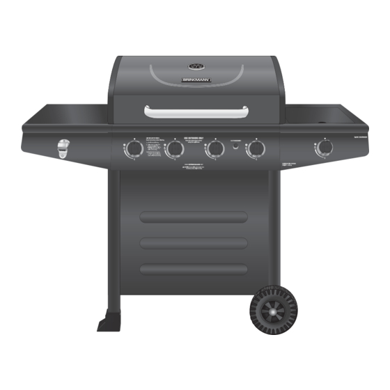
- Page 30 ® Brinkmann 3420 (Assembled)
-
Page 32: Contact Information
4 Burner Gas Grill under the terms of this warranty, please call Customer Service Department at 0800 9520101. A receipt will be required. The Brinkmann Corporation will not be responsible for any grills forwarded to us without prior authorization. EXCEPT AS ABOVE STATED, THE BRINKMANN CORPORATION MAKES NO OTHER EXPRESS WARRANTY.
Need help?
Do you have a question about the 810-3420-A and is the answer not in the manual?
Questions and answers