Advertisement
Quick Links
Anleitungen
D
Instructions
F
Instructions
GB
Instrukties
NL
Für Service: (49) 6838/907-200
D
For Service: 0800-31-78-47
GB
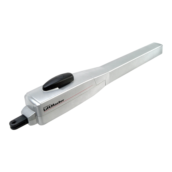
Drehtorantrieb HC300/HC400
Drehtoröffner Steuerelektronik
Automatisme portail à battants HC300/HC400
Automatisme portail à battants Commande électronique
Swing Gate Opener HC300/HC400
Swing Gate Opener Logic Control Box
Vleugelpoortaandrijving HC300/HC400
Vleugelpoortaandrijving Besturingselektronica
F
NL
Pour Service: 03-87-95-39-27
Voor Service: 020-684-7978
™
Advertisement


Need help?
Do you have a question about the HC300 and is the answer not in the manual?
Questions and answers