
Subscribe to Our Youtube Channel
Related Manuals for Firefly cygnus hpg


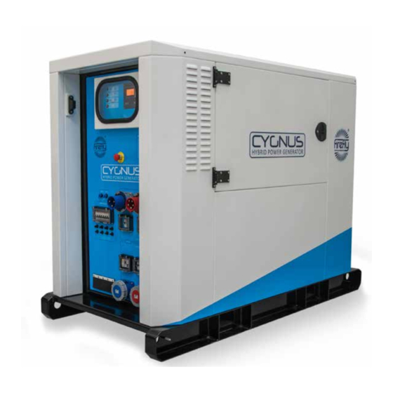
Summary of Contents for Firefly cygnus hpg
- Page 1 CYGNUS HPG 12-24 KV A User manual v1.6 For use with the following models: CYG3/12/37/AGM CYG3/12/50/AGM CYG3/18/37/AGM CYG3/18/50/AGM CYG3/24/37/AGM CYG3/24/50/AGM www.fireflycleanenergy.co.uk...
-
Page 2: Table Of Contents
2.4.4 Connect The AC Output 3 General Operation 3.1 Turning The Power On 3.1.1 Description Of The Power Modes 3.1.2 Switching On The Cygnus HPG 3.1.3 Monitoring Battery Bank State of Charge 3.1.4 Emergency Stop Button 3.1.5 Turning Off The Cygnus HPG 3.1.6 Disconnecting Cygnus HPG... - Page 3 TABLE OF CONTENTS 3.4 Care And Maintenance 3.4.1 General Cleaning 3.4.2 Caring For The Battery Bank 3.4.3 Testing Cygnus HPG 3.5 Troubleshooting 4 Appendices 4.1 Connecting To A Fuel Generator For Automatic Stop/Start 4.1.1 Control Panel Auxiliary Connections 4.1.2 Bus Bar Auxiliary Connection 4.2 Earthing Cygnus HPG 4.2.1 When Used Inline With A Fuel Powered Generator...
-
Page 4: Introduction
European sourced electrical components, your new Cygnus HPG offers sustainable power generation with the reliability that you demand. The purpose of this manual is to introduce you to Cygnus HPG and provide you with a guide to its safe installation and operation. This manual describes how your Cygnus HPG works, will help you with fault finding and examines what key components are doing and why. -
Page 5: Warnings
The following terms are used in this manual to provide greater clarity: • Firefly will be referred to as “The manufacturer”. • The Cygnus HPG Hybrid Power Generator will be referred to as “Cygnus HPG” or “Unit”. • Any items that consume power will be referred to as “Consumers”. -
Page 6: Standards & Regulations
1.5 Disposal & Recycling IP56 Cygnus HPG comprises of components that must be disposed of responsibly. For the sake of the environment many of the components within the unit can be recycled or reused. Firefly will ensure the safe decommissioning and recycling of the unit at no charge if the unit is returned to the manufacturer. -
Page 7: About Firefly
1.7 About Firefly Firefly is the market leading expert in the design and manufacture of off-grid, portable Hybrid Power Solutions for temporary and permanent power applications. Firefly has built its highly regarded reputation within the industry, based on excellent customer service and product reliability. Founded in 2007 the Company continues to develop innovative solutions to cater to the needs of its ever growing customer sectors. -
Page 8: Getting Started
1. Cygnus HPG must be loaded or unloaded using the correct equipment operated by suitably trained personnel. 2. Using the fork pockets, Cygnus HPG can be loaded or unloaded with a suitable fork-lift truck or telehandler. 3. Cygnus HPG can be safely lifted using its integral lifting ring. -
Page 9: Positioning
Refer to lifting equipment’s operation manual for lifting capacity and manufacturer’s operating instructions. Always check the rating plate to ascertain the gross weight of the unit. The unit must remain upright at all times. 2.2.3 Positioning 1. The unit must be positioned upright on a flat, solid surface. Ensure that the unit is not at risk from being submersed in water above the fork pockets. -
Page 10: The Cygnus Hpg Control Panel
2.3 The Cygnus HPG Control Panel Fig. 1 - Control Panel Page 10 CYGHPG12-24-User-Manual-v1.6.indd... - Page 11 1. Mode Selector- Allows switching between the three power routing modes and off 2. Emergency Stop- Press in to immediately halt all operation 3. Auxiliary connections (Generator start)- Provides signals for various applications including the control of a Gen. Set. 4.
-
Page 12: Connecting Cygnus Hpg
2.4.1 Earth attachment: Installing an Earth Rod 1. The Earth Point of Cygnus HPG is an M10 threaded stud with washers and wing nut located on the skid to the right side of the unit. 2. Find a suitable place to drive the earth rod into the ground. The earth rod should be driven down at least half way into the ground using a mallet and placed as near to the unit as possible. -
Page 13: Input Options
1. Ensure that the AC supply being connected to the unit is switched off. 2. Ensure the input breakers are switched off. 3. Ensure that Cygnus HPG is in Mode 4: Off. 4. Ensure that the CEE Form connectors are dry; wipe off any excess moisture with an absorbent cloth. - Page 14 8. Switch on the unit’s input breaker. 2.4.3.3 Connecting by Hard Wiring Into The AC Input Bus Bar 1. Before any power connections are made, ensure that Cygnus HPG is in Mode 4: Off. See "3.1.1 Description Of The Power Modes" on page 2.
-
Page 15: Fig. 5 - Inputs, Outputs And Circuit Breakers
Replace tighten nuts. 63 A Single Phase Input 63 A Three Phase Input Single Phase Input MCB Three Phase Input MCB Single Phase Output RCD Three Phase Output RCD Single Phase Output MCB Three Phase Output MCB 63 A Single Phase Output 10 63 A Three Phase Output Fig. -
Page 16: Connect The Ac Output
2.4.4 Connect The AC Output 2.4.4.1 Connecting with CEE Form Industrial Plugs 1. Before any power connections are made, ensure that Cygnus HPG is in Mode 4: Off. See "3.1.1 Description Of The Power Modes" on page 2. Ensure that the output breakers are switched down into the off position. -
Page 17: General Operation
3.1.1 Description Of The Power Modes Cygnus HPG has three different modes of operation. The modes control how the inverters are configured and how the power is routed through the unit. The mode is selected by depressing a single button behind the top control panel door. -
Page 18: Switching On The Cygnus Hpg
All primary internal circuitry is disabled. Cooling systems remain operational. 3.1.2 Switching On The Cygnus HPG The relevant power mode must first be decided upon. This will depend on the power requirements of the installation. 1. Ensure that the Emergency stop button is released by rotating it clockwise. -
Page 19: Monitoring Battery Bank State Of Charge
3.1.3 Monitoring Battery Bank State of Charge The status of the unit’s internal battery bank is monitored using the RCC 03’s controls. To access the controls 1. Open the control centre door using the supplied key- see "Fig. 6 - 5 mm Double Barb Key"... -
Page 20: Emergency Stop Button
1. If there is an emergency and it is necessary to stop the power from the unit, depress the Emergency Stop Button (Fig. 1, C6) on the Control Panel. 2. The unit will then shut down. Cygnus HPG can not be switched again... -
Page 21: Disconnecting Cygnus Hpg
3.2 Charging From An AC Supply The unit can be charged via a 220 - 240 V AC supply from either the AC grid supply or a secondary power system. To connect an AC supply to Cygnus HPG: 1. Connect the AC Input (See "4.1 Connecting To A Fuel Generator For... -
Page 22: System Settings
3.3 System Settings W A R N I N G The AC Output Voltage and System Earthing parameters must only be changed by a competent electrical engineer. The following settings are available to users through the RCC-03 controls. Further details available on request. Basic Settings Maximum current of AC Source Min: 2... - Page 23 Contact active on event Xtender is off For info only Contact active with inverter power or smart boost Inverter power level 1 activate Default: Yes Power level 1 (% pNom) Min: 20 Default: 80 Max: 120 Time delay (minutes) Min: 0 Default: 0 Max: 60 Inverter power level to deactivate (%...
- Page 24 System Earthing (Earth-Neutral) - Danger! Adjustments should only be made by qualified personnel Prohibited ground relay No (Default) Continuous neutral No (Default) RCC Settings Language English French German Spanish Time Date User Level Unlock code required- available from manufacturer on request. Save &...
-
Page 25: Care And Maintenance
W A R N I N G If Cygnus HPG fails the relevant tests, do not use or open the unit. It must only be opened by a qualified service engineer. It is recommended that a full service is performed every two years in order to ascertain the condition of your system. -
Page 26: Troubleshooting
Possible Cause(s) Suggestion Check that the MCBs and RCDs are pushed Power is on at the Cygnus HPG but the The output MCBs or RCDs may not be up to the on position and that the relevant consumers are not receiving any power switched on output LEDs are illuminated. -
Page 27: Appendices
4.1 Connecting To A Fuel Generator For Automatic Stop/Start Auxiliary connections are provided which allow the automatic control of a fuel powered generator. These allow Cygnus HPG to control the start up and shut down of the attached generator under pre-programmed conditions using the RCC-03. -
Page 28: Earthing Cygnus Hpg
4.2.3 When Charging A Standalone Generator from An AC Source While a standalone Cygnus HPG is being charged from an AC source such as a CAUTION: Do not dispose of three phase grid connection or fuel powered generator which will be batteries in a fire. - Page 29 4.4 Variable RCD A Variable RCD (Residual Current Device) Circuit Breaker is provided as part of the AC output protection system. It allows for the adjustment of the sensitivity and time delay before the Variable RCD trips. W A R N I N G The Variable RCD is a vital safety device providing protection from potentially fatal electrocution.
-
Page 30: Technical Data
This document was updated July 2015. While every effort has been made to ensure accuracy, no responsibility can be accepted for errors or omissions. Data may change, as well as legislation, and you are strongly advised to obtain copies of the most recently issued regulations, standards and guidelines. This document is not intended to form the basis of a contract. Firefly has a policy of continuous product improvement and reserves the right to change specifications without notice.©2015 Firefly . - Page 31 Fig. 5 Fig. 6 Firefly - Clean Energy, Unit 20, Cliffe Industrial Estate, South Street, Lewes, BN8 6JL, UK T: +44 (0)1273 40 95 95 F: +44 (0)1273 40 95 96 W: www.fireflycleanenergy.co.uk E: info@fireflyce.co.uk Firefly_Cygnus_Three_HPG_AGM_TDS_v4.4 - 29 July 2015 11:49 AM...
Need help?
Do you have a question about the cygnus hpg and is the answer not in the manual?
Questions and answers