Table of Contents
Advertisement
Safety, Operation & Maintenance Manual
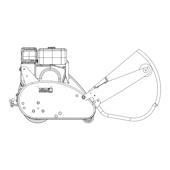
Ransomes MATADOR 71 - Engine HONDA GX160-K1
Series: EH4
Product code:
LDDD704
WARNING: If incorrectly used this machine can
cause severe injury. Those who use and maintain
this machine must be trained in its proper use,
warned of its dangers and must read the entire
manual before attempting to set up, operate, adjust
or service the machine.
GB
RJL 100 September 2014
United
Kingdom
WARNING
25068G-GB (R1)
®
Advertisement
Table of Contents

Related Manuals for Ransomes Matador


Summary of Contents for Ransomes Matador
- Page 1 25068G-GB (R1) ® Safety, Operation & Maintenance Manual Ransomes MATADOR 71 - Engine HONDA GX160-K1 Series: EH4 Product code: LDDD704 WARNING WARNING: If incorrectly used this machine can cause severe injury. Those who use and maintain this machine must be trained in its proper use,...
-
Page 2: Table Of Contents
..................53 ASHBOARDING ..................54 ARCELLING ..................55 UTTING ..................... 55 CALPING ..................56 TRAGGLERS ....................57 TREAKS ..................57 INDROWING ..............58 IFLING LINING ..............60 ISMATCHED UTTING NITS GUARANTEE ..................61 UARANTEE © Ransomes Jacobsen Limited. All Rights Reserved... -
Page 3: Mportant
INTRODUCTION 2 IMPORTANT__________________________________________________________ The Ransomes MATADOR is a Petrol engined Pedestrian REEL mower. The traction drive and the cutting unit are Chain Driven. IMPORTANT: Do the maintenance indicated in this manual to make sure that the quality of cut is kept at a high level. -
Page 4: Roduct Identification
PRODUCT IDENTIFICATION ___________________________________________ Maximum front axle load in Kg (for machines being driven West Road on the highway) Ransomes Europark Ipswich IP3 9TT Gross weight (mass) in Kg England Maximum rear axle load in Kg (for machines being driven on... -
Page 5: O F Service Life
“General discarded materials” area. • Do not burn discarded materials. Change the machinery records to show that the machine is not in service and is discarded. Supply this serial number to Ransomes Jacobsen Warranty Department to close their records. en-5... -
Page 6: Parts Manual
2 INTRODUCTION PARTS MANUAL ______________________________________________________ In compliance with the ISO14001 standard, Ransomes Jacobsen Limited does not send a paper parts manual with every product. To refer to a parts list for this mower you have four options: Website – www.ransomesRansomes Jacobsen.com. Select the “GENUINE PARTS” tab followed by the “ONLINE PARTS LOOK-UP”... - Page 7 INTRODUCTION 2 ASSEMBLY __________________________________________________________ The Mower is fitted to a container at the factory and will need assembly before operation. Some tools will be needed for assembly. Discard the container according to the applicable local environmental requirement. Remove the mower from the container. The handles are found around the chassis - Figure The handles engage on the lug shaft (A).
- Page 8 2 INTRODUCTION NOTES en-8...
-
Page 9: How To Operate Safely
Manuals in additional languages may be available on the Jacobsen or Ransomes Jacobsen website. Read all of the instructions for this mower carefully. Know the controls and the correct operation of the equipment. -
Page 10: Operation
3 SAFETY 3.1.3 Operation Never operate the engine without enough ventilation or in an enclosed area. The carbon monoxide in the exhaust fumes can increase to dangerous levels. Never carry passengers. Keep other persons or animals away from the mower. Disengage all drives and engage the parking brake before you start the engine. -
Page 11: Maintenance And Storage
SAFETY 3 3.1.4 ROPS The ROPS is a safety device. Keep the ROPS in the vertical and locked position. Always use the seat belt when you operate the mower. Make sure the seat belt can be released quickly in an emergency. Only operate the mower with the ROPS in the folded position on flat and level surfaces when necessary. - Page 12 3 SAFETY Charge the battery in an area with good airflow. The battery can release hydrogen gas that is explosive. To prevent an explosion, keep any device that can cause sparks or flames away from the battery. Disconnect the battery charger from the power supply before you connect or disconnect the battery charger to the battery.
-
Page 13: Important Safety Notes
By following all instructions in this manual, you increase the life of your machine and keep its maximum performance. Adjustments and maintenance must always be done by an approved technician. If additional information or service is needed. Contact your Authorized Ransomes Jacobsen Dealer, who knows the latest methods to service this equipment and can give that service. - Page 14 2006/42/EC Sections 3.2.2, Seating & 3.4.3, Rollover. (ANSI B71.4-2012 section 20.7) Ransomes Jacobsen Limited Recommends That The Owner/User Of The Machine Completes A Local Risk Assessment Of The Machine To Find Any Conditions That Do Not Follow This Rule. E.g. When You Drive The Machine Next To Water Or On The Highway.
- Page 15 SAFETY 3 WARNING Vibration Exposure Limits Exposure limits are calculated as a combination of the vibration level (magnitude) of the tool and the Daily Exposure Time (Trigger Time). E.g. A product with 5m/s² vibration can be used up to 2 hours/day to reach the EAV and up to 8 hours/day to reach the ELV.
- Page 16 3 SAFETY NOTES en-16...
-
Page 17: Specification
SPECIFICATIONS 4 ENGINE SPECIFICATION ______________________________________________ Honda 2.95kW (4HP)/ 2700 RPM, single cylinder, air cooled 4 stroke OHV petrol Type: engine 25° inclined cylinder, horizontal shaft. Model: GX160 K1-QX4 Maximum Speed: 2700 ± 50 RPM (No load). Idle Speed: 1400 + 200 -150 RPM Oil Sump Capacity: 0.6 litres (1 Imp Pints) (0.63 US qts) Fuel:... -
Page 18: Achine Specification
4 SPECIFICATIONS MACHINE SPECIFICATION _____________________________________________ Frame construction: Pressed Steel welded fabrication. Transmission: By heavy roller chains. Clutches: Transmission clutch. Separate cylinder clutch. Separate landroll clutch. Front roll: One piece steel roll running on ball bearings. Landroll: Two piece smooth cast iron with bevel gear differential. Cutting cylinder: All welded 5 knife cylinder running on ball bearings. -
Page 19: Vibration Level
Information Supplied for Physical Agents Directive 2002/44/EC By reference to: Hand/Arm Standards: BS EN ISO 5349-1 (2001) BS EN ISO 5349-2 (2002) Max. LH or RH Ransomes Matador 71 Accelerations m/s² Series EH4 Hand / Arm Acceleration Mean Value of X, Y, Z Aeq Level 0.00 ±... -
Page 20: Noise Level
4 SPECIFICATIONS NOISE LEVEL________________________________________________________ When the machine was tested for sound pressure (Operator Ear). The Machinery Safety Directive 2006/42/EC Exposure Of Workers To The Risks Arising From Physical Agents (Noise) Directive 2003/10/EC By compliance to: The Lawnmower Standard BS EN ISO 5395:2013 Sound Pressure Standard EN ISO 3746: 2010 Measured Sound Pressure 87 dB(A) ±... -
Page 21: Utting Performance
A.P.I. Classification SJ grades. [10W-30] TEMPERATURE OIL VISCOSITY -15°C to 40°C SAE 5W-30 4.10 ACCESSORIES ______________________________________________________ 4.10.1 TRAILING SEAT KIT A trailing seat is available.It is attached by a one pin hitch. Only use a Ransomes Jacobsen trailing seat (LMAA747) with these machines en-21... -
Page 22: C Ertificates O F C Onformity
4 SPECIFICATIONS 4.11 CERTIFICATES OF CONFORMITY _______________________________________ Ransomes Jacobsen Limited West Road, Ransomes Europark, Ipswich, England, IP3 9TT LDDD704 Ransomes Matador 71 Pedestrian Reel Mower EH400301 - EH499999 Honda GX160 K1-QX4 2.95kW (4HP)/ 2700 RPM 71cm 2006/42/EC (Machinery Directive) 2004/108/EC (EMC) - Page 23 BS ISO 2631-1:1997 (Vibration W/B) ANSI B71.4-2012 Ransomes Jacobsen Limited West Road, Ransomes Europark, Ipswich, England, IP3 9TT 1st September 2014 Signature of the person empowered to draw up the declaration on behalf of the manufacturer, holds the technical documentation and is authorised to compile the technical file, and who is established in the Community.
- Page 24 A gyártó üzleti neve és teljes címe Ragione sociale e indirizzo completo del fabbricante Uzņēmuma nosaukums un pilna ra otāja West Road, Ransomes Europark, adrese Verslo pavadinimas ir pilnas gamintojo adresas Isem kummerċjali u indirizz sħiħ tal-fabbrikant Nazwa firmy i ny adres producenta Nome da empresa e endereço completo do fabricante...
- Page 25 és erről nem nyilatkoznak. Ransomes Marquis 51 & 61 La quasi-macchina non deve essere messa in servizio finché la macchina finale in cui deve essere incorporata non è stata dichiarata conforme, nel caso, alle disposizioni della Direttiva LDAA500, LDAA510, LDCB600 &...
- Page 26 4 SPECIFICATIONS NOTES en-26...
-
Page 27: Decals Ec
5 DECALS 5.1 SAFETY DECALS _____________________________________________________ 009034910 009034890 009034920 009034900 009114240 009034970 009034910 Read Operator's Manual. 009034890 Keep a Safe Distance from the Machine. 009034920 Stay Clear of Hot Surfaces. 009034900 Do Not Open or Remove Safety Shields While the Engine is Running. 009114240 Unleaded Petrol, Safety Alert. -
Page 28: Nstruction Decals Ec
DECALS 5.2 INSTRUCTION DECALS _______________________________________________ 4130883 Operator Presence Control (OPC) & Landroll clutch / Parking Brake en-28... -
Page 29: Opc
6 CONTROLS OPERATOR PRESENCE CONTROL (OPC) ___________________________ The OPC control is on the right-side handle bar. To operate, press the button (B) and pull the lever (A) to engage the drive. To disengage the OPC, release lever A. Button (B) will spring into position and prevent the operation of Lever (A). -
Page 30: Hrottle Control
CONTROLS THROTTLE CONTROL ____________________________________________ To change the cutting speed, use the hand lever (D).To increase the engine turns, move the hand lever (D) down. To decrease the engine turns, return the hand lever (D) to the Low Idle position. BRAKE RELEASE LEVER _________________________________________ To apply the landroll brake, move the hand lever (E) to the top position. -
Page 31: C Ylinder C Lutch
6 CONTROLS CYLINDER CLUTCH LEVER _______________________________________ To engage the cylinder clutch, move the lever (F) down. To disengage the cylinder clutch, return the hand lever to the start position. IGNITION CUT-OUT SWITCH _______________________________________ The ignition switch is found on the front of the engine. Move the switch (A) to the ‘|’... - Page 32 CONTROLS NOTES en-32...
-
Page 33: Inspection
7 OPERATION 7.1 DAILY INSPECTION ____________________________________________________ CAUTION Make sure that the Engine and exhaust are cold. Do not check with a warm engine. Engage the parking brake and make sure the cutting cylinders are stopped. Check the complete unit. Look for worn or loose hardware, missing or damaged components, fuel or oil leaks. -
Page 34: Operator Presence And Safety Interlock System
OPERATION 7.2 OPERATOR PRESENCE AND SAFETY INTERLOCK SYSTEM_________________ The OPC system controls the primary drive clutch. You can start the engine, but the drive will not engage until the OPC system is in operation (See 6.1). The machine will not drive until the OPC is engaged. To engage the Cutting cylinder, operate the lever (F See 6.5). -
Page 35: Operation Of The Machine
7 OPERATION 7.3 OPERATING PROCEDURE ______________________________________________ CAUTION To prevent injury, always wear eye protection, leather work shoes or boots, a hard hat and ear protection. Do not start the engine with the OPC system engaged. Do not operate the machine or attachments with loose, damaged or missing components. Mow when the grass is dry First mow a test area to understand the operation of the machine and control levers. - Page 36 OPERATION CAUTION Disengage the drives, engage the parking brake and stop the engine. Before you clean, adjust or repair this equipment. WARNING DO NOT USE ON GRADIENTS OF MORE THAN 18° When you operate on gradients, or near drop off points, decrease the speed and be careful. Read the Section 3.7.
-
Page 37: How To Start The Engine
7 OPERATION 7.4 OPERATION OF THE MACHINE __________________________________________ Read the Safety Instructions. HOW TO START THE ENGINE FOR THE FIRST TIME • Remove the sump filler cap and with the machine on level ground. Make sure that the sump is filled with oil. - Page 38 OPERATION NOTES en-38...
-
Page 39: Eight Of Cut Setting
8 ADJUSTMENTS HEIGHT OF CUT SETTING ____________________________________________ The cutting height is set by the position of the front rolls in relation to the bottom blade. To set the height of cut, adjust the front roll. Use the height of cut bar (A) to set accurately the height of cut. -
Page 40: Cylinder To Bottom Blade Adjustment
ADJUSTMENTS CYLINDER TO BOTTOM BLADE ADJUSTMENT__________________________ The cutting cylinder must be set to engage correctly with the bottom blade. To check: Tilt the machine backward, hold a thin piece of paper between the edge of the blade and spiral cutters. Turn the cutting cylinder manually. The paper must be cut equally along the length of the bottom blade. -
Page 41: Adjustment
8 ADJUSTMENTS LANDROLL CLUTCH ________________________________________________ The Landroll clutch lever is found on the left-side handle bar. To engage the clutch and stop the drive, pull the lever in. To disengage the clutch and drive the landroll release the lever. Adjustment: Release the locknut (A). -
Page 42: Landroll Scraper
ADJUSTMENTS LANDROLL SCRAPER _______________________________________________ To adjust the scraper, loosen the screws (A) at each end of the scraper. Adjust the scraper position and tighten the screws. CHAIN ADJUSTMENTS ______________________________________________ Remove the chain case cover to access the chains. The chains need a degree of free movement Measure at the center of the longest side. -
Page 43: Adjustment
Apply some carborundum grinding paste* on the spiral cutters. Available from your Ransomes Jacobsen supplier. Rotate the cutting cylinder in the reverse of the cutting stroke. Use a socket spanner and brace on the screw (E). NOTE: During the ‘back lapping’ operation, check the setting of the cutting cylinder to the bottom blade. If necessary make an adjustment. -
Page 44: Otes
ADJUSTMENTS NOTES en-44... - Page 45 9 ACCESSORIES 9.1 TRAILING SEAT _______________________________________________________ A trailing seat is available.It is attached by a one pin hitch. Only use a Ransomes Jacobsen trailing seat (LMAA747) with these machines. INSTALLATION Position trailing seat behind the machine. Rotate the lock pin forward.
- Page 46 ACCESSORIES NOTES en-46...
-
Page 47: Djustment
10 MAINTENANCE MAINTENANCE AND LUBRICATION CHART Interval Item Section First Month or 20 hours Change Engine Oil 11.3 Check Engine Oil Level 11.1 Check Air Filter Element Each day 10 hours 10.2 Check Engine for Dirt 10.1 Clean Air Filter Element. If necessary - Replace. * 10.2 First 50 hours Check and Adjustment of Landroll Clutch... - Page 48 10 MAINTENANCE These figures are for instruction only. If the hours of use in any calendar period, are more than those given, use the work hours as your maintenance schedule. 10.1 ENGINE DAILY (EVERY 8 WORKING HOURS) ______________________________ Make sure the Engine and controls are kept clean, free from grass cuttings and dirt.
-
Page 49: Weekly:
10 MAINTENANCE 10.2 ENGINE WEEKLY: (EVERY 50 WORKING HOURS) __________________________ Air cleaner two element type): Remove the wing nut and the air cleaner cover. Remove the elements and disassemble. Carefully check both elements for damage. Replace if dirty or damaged. Clean the Foam Element: Wash the element in a solution of detergent and warm water. - Page 50 10 MAINTENANCE 10.3 CLUTCH AND LAYSHAFT COVER _______________________________________ Release the screws (A) and remove the drive cover. Clean the Primary clutch and layshaft area. When completely clean, replace the drive cover and tighten the screws (A). 10.4 LANDROLL BRAKE____________________________________________________ Check the brake band condition and adjust, see 8.11. en-50...
- Page 51 11 LUBRICATION The recommended lubricants are recorded on Section 4.4 These figures are for instruction only. If the hours of use in any calendar period, are more than those given, use the work hours as your lubrication schedule. 11.1 ENGINE DAILY: (EVERY 8 WORKING HOURS) ___________________________ Make sure that the machine is on level ground.
- Page 52 11 LUBRICATION 11.4 MACHINE _________________________________________________________ Before you use the machine for the first time, lubricate A,B and C. Use the recommended grease. A Cutting cylinder bearings B Landroll C Front roll spindle Oil all linkages, drive chains and pivot points etc. NOTE: The landroll clutch and drive is found below the chain case cover.
-
Page 53: Quality Of Cut
12 QUALITY OF CUT QUALITY OF CUT PROBLEM SOLVING _________________________________ Make a “test cut” to check the performance of the 1. Cut (Ground) Speed. mower before you start the repairs. This area must have turf conditions that are known 2. The Reel Bearing Condition And Adjustment and do not change across the area. -
Page 54: M Arcelling
12 QUALITY OF CUT 12.2 MARCELLING ______________________________________________________ Marcelling, like washboarding, is a repeated pattern of different cutting heights, that causes an appearance that is like a wave. In most cases, the wave tip-to-tip distance is 2 inches (5 cm). TN0220 NOTE: Arrow indicates direction of travel. -
Page 55: Step Cutting
12 QUALITY OF CUT 12.3 STEP CUTTING _____________________________________________________ Step cutting occurs when the grass is cut higher on one side of a reel than the other side. Step cutting can occur when one cutting unit is higher than another cutting unit. The wear of mechanical parts or an incorrect roller or height-of-cut adjustment can cause step cutting. - Page 56 12 QUALITY OF CUT 12.4 SCALPING ________________________________________________________ Scalping is a condition in which a areas of grass are cut shorter than the adjacent areas. The area can be light green or brown. A low height-of-cut (HOC) setting or turf that is not level can cause scalping. TN0222 NOTE: Arrow indicates direction of travel.
- Page 57 12 QUALITY OF CUT 12.5 STRAGGLERS ______________________________________________________ Stragglers are separated blades of grass that are not cut, or are cut incorrectly. TN0223 NOTE: Arrow indicates direction of travel. Possible Cause Solution The bedknife is incorrectly adjusted. Adjust reel-to-bedknife setting. The edges of the reel or bottom blade are not sharp. Sharpen or replace the reel blade and bedknife as necessary.
- Page 58 12 QUALITY OF CUT 12.6 STREAKS _________________________________________________________ A streak is a line of grass that is not cut. The cause of a streak can be a damaged or bent bedknife. TN0224 NOTE: Arrow indicates direction of travel. Possible Cause Solution Damaged bedknife.
-
Page 59: W Indrowing
12 QUALITY OF CUT 12.7 WINDROWING ______________________________________________________ Windrowing is the deposit of clippings increased at one end of the cutting unit or between two cutting units. Windrowing can make a line in the direction of travel. TN0225 NOTE: Arrow indicates direction of travel. Possible Cause Solution The grass is higher than the level at which the... -
Page 60: Rifling Or Tramlining
12 QUALITY OF CUT 12.8 RIFLING OR TRAMLINING____________________________________________ Rifling or tramlining is a pattern of different cutting heights, that causes a cut appearance like a wave. The cause of rifling can be a heavy contact point across a reel or a bedknife. NOTE: Arrow indicates direction of travel. - Page 61 13 GUARANTEE 13.1 GUARANTEE__________________________________________________________ WARRANTY Warranty is subject to specific terms and conditions, e.g. wearing parts, unapproved modifications, etc. are not included. For a full set of warranty conditions, contact your local dealer or distributor. SERVICE A network of authorised Sales and Service dealers has been established and these details are available from your supplier.
- Page 62 13 GUARANTEE NOTES en-62...
- Page 64 Europe & Rest of The World Except North & South America Ransomes Jacobsen Limited West Road, Ransomes Europark, Ipswich, IP3 9TT English Company Registration No. 1070731 www.ransomesjacobsen.com North & South America Jacobsen, A Textron Company 11108 Quality Drive, Charlotte, NC 28273, USA...
Need help?
Do you have a question about the Matador and is the answer not in the manual?
Questions and answers