
Subscribe to Our Youtube Channel
Related Manuals for Interlogix TVD-2202


Summary of Contents for Interlogix TVD-2202
-
Page 1: Installation Guide
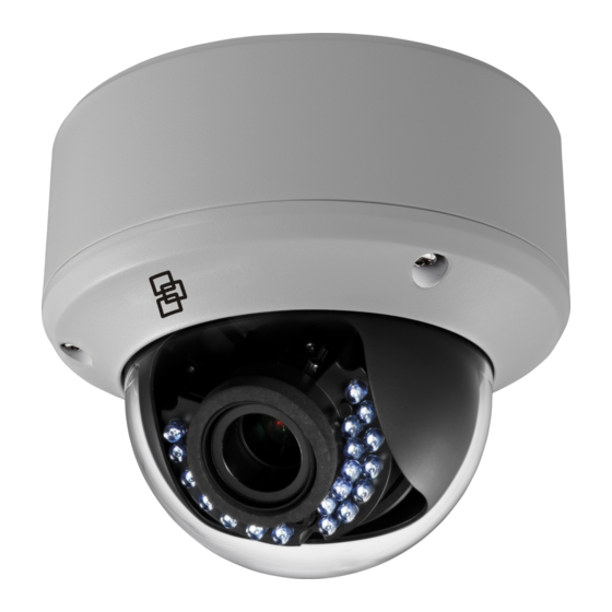
TruVision IR Dome Camera TVD-2202/TVD-4202 Installation Guide P/N 1072923 • REV A • ISS 10FEB15... -
Page 3: Table Of Contents
Contents Product overview 2 Camera description 4 Installation 5 Programming 9 Specifications 10 Setup menu 11 Regulatory information 12 Installation Guide... -
Page 4: Product Overview
Product overview This is the TruVision IR Dome Camera Installation Guide for models TVD-2202/TVD-4202. This guide describes a standard installation. Package contents: Camera with power 4 M4 screws (4 x and video output 25 mm) and 4 dry cables wall anchors (Ø7.5... - Page 5 3 M4 screws (3 x Hex wrench 25 mm) screws to install the camera to the back box • WEEE and Battery Monitor output cable Disposal Installation Guide Installation Guide...
-
Page 6: Camera Description
Camera description Dome liner Power cable Bubble Video cable Auxiliary video Lens output Back box Menu button Installation Guide... -
Page 7: Installation
Installation To install the camera: Using the template, place it level against the mounting surface and mark the position of the mounting holes. Following all local codes, drill and prepare the mounting holes. Remove the camera from its back box. Loosen the three set screws on the edge of the bubble with the supplied hex wrench. - Page 8 Secure the back box to the ceiling with the supplied screws. Connect a 75-ohm coaxial video cable to the video cable and a power supply to the power cable. Align the camera with the back box and tighten the set screws to secure the camera to the back box.
- Page 9 Adjust the surveillance angle: View the camera image on a monitor. Rotate the panning table to adjust the pan direction [0 to 355°]. Loosen the tilting lock screw. Rotate the tilting table to adjust the tilt direction [0 to 90°]. Tighten the tilting lock screw.
- Page 10 Zoom and focus adjustment. View the camera image using the monitor. Loosen the zoom lever and move the screw between T (Tele) and W (Wide) to obtain the appropriate angle of view. Tighten the zoom lock screw. Loosen the focus lever and move the screw between F (Far) and N (Near) to obtain the optimum focus.
-
Page 11: Programming
Zoom Focus Programming Once the camera hardware has been installed, the camera can be configured by using the built-in OSD button or a TVS-C200 controller (purchase separately). The Setup menu provides access to the camera configuration options. See page 11 for an overview of the menu. -
Page 12: Specifications
To access the Setup menu: Press the OSD control button (Enter) to access the Main menu and its submenus. Push the button up, down, left and right to move between menu options. Press the OSD control button to select an option. -
Page 13: Setup Menu
Setup menu Installation Guide... -
Page 14: Regulatory Information
Regulatory information Copyright: © 2015 United Technologies Corporation. Interlogix is part of UTC Building & Industrial Systems, a unit of United Technologies Corporation. All rights reserved. Trademarks and patents: Trade names used in this document may be trademarks or registered trademarks of the manufacturers or vendors of the respective products. - Page 15 For proper recycling, return this product to your local supplier upon the purchase of equivalent new equipment, or dispose of it at designated collection points. For more information see: www.recyclethis.info. Contact information: For contact information, see www.interlogix.com or www.utcfssecurityproducts.eu Installation Guide...
Need help?
Do you have a question about the TVD-2202 and is the answer not in the manual?
Questions and answers