Table of Contents
Advertisement
Advertisement
Table of Contents
Troubleshooting

Related Manuals for Wood master FORCE 30


Summary of Contents for Wood master FORCE 30
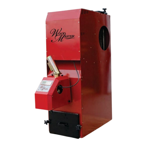
- Page 1 WOODMASTER FORCE 30 Retain this manual Pellet Pellet Furnace Furnace Powered by the Renovator Pellet Burner www.woodmaster.com / 800-932-3629 / Manual PN: 7994-805 Northwest Manufacturing, Inc / 600 Polk Ave SW / Red Lake Falls, MN 56750 Rev:2.6/Software V20...
-
Page 2: Table Of Contents
Warranty ................ 37-40 Terms .................. 41 Notes ................42-43 Thank you for purchasing the Force 30 furnace from WoodMaster. This product was designed to deliver easy, trouble free operation for years to come. Check out other WoodMaster heating products at www.woodmaster.com, or our line of quality pellet grills at www.woodmasterpelletgrills.com. -
Page 3: Safety
• During operation only touch the PLC Temperatures at other points (for example, chimney, access doors, ducting...) can be very high. • The Force 30 must be operated exclusively according to the guidelines for planning, assembly, regulations, statutes and product related instructions. The manufacturer is not liable for damages and their results, if they occurred due to improper assembly, operation, application and also inadequate maintenance and cleaning. -
Page 4: Safety
Safety Standards Guardian info: Solid Fuel Burner System. Listed by Guardian Fire Testing Laboratories Inc. Tested and listed to THE Applicable Sections of UL-391, ETLM 78-1, ASTM-E 1509 & CAN/CSA-B366.1 EPA EXEMPT PER 40CFR60.53A, METHOD 28A Force 30 Owners Manual 2015... -
Page 5: Technical Features
10. High quality and attractive outer shell amount of heat to the air chamber 5. Triple Pass flue tube insures the heat stays in your home and not out the stack (6”) 2015 Force 30 Owners Manual... -
Page 6: Fuels
Note: Pellets should be stored in a dry area and should not be allowed to get wet. Handle pellets with care. Note: Each time you change brand/quality of pellets you may also have to change the start dose and feed rate of the burner. Force 30 Owners Manual 2015... -
Page 7: Installation
Location Your Force 30 can only be installed indoors. Ensure that the floor that the furnace is to be placed is level and able to support the weight of the furnace plus the additional weight of the fuel. Ensure the feet are in the bot- tom of the furnace. - Page 8 Place a gasket material, i.e. fiberglass rope, around the burner connection hole as shown. Note: Some models will have a gasket attached to the mount- ing bracket from the factory. Skip this step if your bracket has the gasket installed. Force 30 Owners Manual 2015...
- Page 9 Installation Fasten the mounting bracket to the furnace with the supplied hardware. Do not tighten at this time. Slide the burner into the mounting bracket. Secure the burner to the mounting bracket. 2015 Force 30 Owners Manual...
- Page 10 E. To Temperature Sensor (not used if thermostat kit 720-0006 is to be used.) Not shown here: Draft controller connections and the air compressor connections. The protective cover on the burner cannot be re- moved without disconnecting these cables. Force 30 Owners Manual 2015...
- Page 11 Note: The auger head may have a slightly different ap- pearance than the one shown in the pictures. Assembly of the auger will not change. Slide the T-pipe onto the auger tube and fasten them together using the screw indicated by the arrow. 2015 Force 30 Owners Manual...
- Page 12 T-pipe. Fasten the screw shown to lock the inlet pipe in place. Slide the blue tube to the outlet of the T-pipe, and the cap on the end of the inlet pipe. The auger is now ready to be installed. Force 30 Owners Manual 2015...
- Page 13 The legs will be on the inside of the hopper, with the skins screwed to the outside. Place the lid of the hopper on the hopper when assem- bly is complete. DO NOT remove during operation. 2015 Force 30 Owners Manual...
- Page 14 Using the provided bolts and wash- ers secure the bottom to the braces on the legs, do not tighten the bolts until the auger is in place to allow for adjustments. Exploded Assembly View Force 30 Owners Manual 2015...
- Page 15 “U” bolts. DO NOT TIGHTEN THE “U” BOLTS AT THIS TIME! Attach the boot to the bottom of the side hopper. Do not tighten the clamp on the boot at this time. 2015 Force 30 Owners Manual...
- Page 16 Raise the leg supports to a point just below the intake auger tube. Tighten the “u” bolts on the leg supports to secure the legs to the leg supports. Force 30 Owners Manual 2015...
- Page 17 Northwest Manufacturing, Inc. offers an adapter (Part Number: 0020-213) that will allow you to con- nect the air hose to a full size air compressor. Whenever the boiler is operational there needs to be a constant supply of compressed air of 80-90 psi available to the burner. 2015 Force 30 Owners Manual...
- Page 18 Filter Box Assembly The filter box is assembled by snapping the panels together. The filter box is attached to the Force 30 with an adapter plate. Secure the plate to the furnace before installing the fan and filter box. CAUTION: Edges of the filter box panels are sharp! Fasten the end panel with the two side panels.
- Page 19 NOTE: All wiring should be done by qualified persons. Once the blower is secured and wired, place the filter box over the blower and secure it to the mounting plate with the supplied screws. The ducting system should be installed by qualified persons. 2015 Force 30 Owners Manual...
- Page 20 The chimney must follow all state and local codes. The Chimney should be installed by a qualified professional. Your Force 30 can be vented into an existing chimney as long as the chimney fits the necessary criteria, and does not service any other appliance.
- Page 21 Once the burner has been properly tuned, fill out the warranty registration card at the back of this manual and return it to Northwest Manufacturing. Testing Location 2015 Force 30 Owners Manual...
-
Page 22: Operation
The burner is not adjusted from the factory. The burner has to be adjusted with a flue gas instrument the first time the burner is fired and after a change in fuel brand/quality. NOTE: The Force 30 is shipped with a protec- tive coating on the heat exchanger to prevent corrosion. - Page 23 PLC on the burner. If a wall mounted thermostat is used, disconnect the temperature sensor. If a wall mounted thermostat is used, the selected value can no Menu/Ok longer be changed in this menu, and is instead controlled by the thermostat. 2015 Force 30 Owners Manual...
- Page 24 4 until the PLC is reset. If the problem persists, there could be a lack of proper draft. Contact your dealer or North- west Manufacturing, Inc. or see the troubleshooting section for further assistance. Menu/Ok Force 30 Owners Manual 2015...
-
Page 25: Operation
If the burner is running, either wait for the thermostat reaches its set point to switch the burner off, or lower the thermostat to switch the burner off. Once the air clean occurs and the combustion fan stop, shut off power to the burner and allow to cool before cleaning. 2015 Force 30 Owners Manual... -
Page 26: Maintenance
Maintenance The Force 30 and Renovator should be cleaned regularly. It is recommended that the furnace and burner should be cleaned every 2 weeks or 1000 pounds of fuel used. CAUTION: THE BURNER AND FURNACE MAY BE HOT! Sweeping the Heat Exchanger Tubes... - Page 27 The Force 30 has an extra large ash box in the bottom of the furnace. The ash box should be checked and emp- tied regularly. The ash box can hold approximately 1-2 weeks worth of ash, or 1000 pounds of pellets that have been burned.
- Page 28 Release the quick latches that hold the sections togeth- er. Be careful as to not damage the gasket between the sections. Force 30 Owners Manual 2015...
- Page 29 Maintenance Lifting Up on the combustion fan, carefully lift the burner assembly off of the fire pot. Carefully remove the gasket. Slide the burn pot out of the boiler. 2015 Force 30 Owners Manual...
- Page 30 Clean any buildup out of the burn pot, and clean all debris out of the air holes. Once clean, insert the inner part of the burn pot into the outer sleeve. Ensure the alignment pins line up. Force 30 Owners Manual 2015...
- Page 31 Once in place, bend the straight end of the pin to lock it in place. Ensure the flame guard moves freely before reinstalling the burn pot in the furnace. Location of the pin. 2015 Force 30 Owners Manual...
-
Page 32: Troubleshooting
3. Safety temp limiter has tripped 3. Check to ensure the chimney is not restricted. 4. There is no power to the burner 4. Check the power to the furnace and the burner. Check the breaker. Force 30 Owners Manual 2015... -
Page 33: Troubleshooting
4. If the problem persists, contact your dealer or North- west Manufacturing, Inc. 10 Amp Circuit Breaker The Force 30 furnace is equipped with a 10 amp circuit breaker. The reset switch is located on the furnace, above the burner. If the problem persists, contact your dealer or Northwest Manufacturing, Inc. -
Page 34: Wiring Diagram
Wiring Pressure Switch Force 30 Owners Manual 2015... - Page 35 Wiring 2015 Force 30 Owners Manual...
-
Page 36: Specifications
**Note: The weights of the components are subject to change, and additional duct work will add weight to the system. ***Note: The hopper weight capacity will vary depending on the quality of the fuel used. Force 30 Owners Manual 2015... -
Page 37: Warranty
FIVE (5) YEARS from the Date of Original Installation. If there is a defect in your properly delivered and installed WoodMas- ter Force 30 in the rst year, WoodMaster will replace the heat exchanger at no cost to the original owner. Northwest Manufac- turing, Inc. - Page 38 MUST be returned to Northwest Manufacturing, Inc. for the purpose of inspection to determine cause of failure. Northwest Manufacturing, Inc. / 600 Polk Ave. SW / Red Lake Falls, MN 56750-5002 (800) 932-3629 • Fax: (218) 253-4409 / www.woodmaster.com Force 30 Owners Manual 2015...
- Page 39 Northwest Manufacturing Inc. PLACE POSTAGE 600 Polk Ave. SW HERE Red Lake Falls, MN 56750 Northwest Manufacturing Inc. 600 Polk Ave. SW Red Lake Falls, MN 56750...
-
Page 40: Warranty
Flue Gas Meter Readings: O2 % ______ CO2 % ______ PPM CO ______ Stack Temp ______ Draft ______ (Degrees Farenheit) (In H20) I have read the owners manual and understand the proper usage of my WoodMaster Force 30. Signature Printed Name... -
Page 41: Terms
Terms Force 30 - Forced air pellet furnace Renovator AKA Burner or Pellet Gun - Combustion chamber that burns pellets Air Compressor - Optional on board air cleaning agent. an optional adapter (pn: 0020-213) can be used to attach the air cleaner to a shop air compressor PLC - Programmable Logic Control - Controls the burner Start Dose - Amount of fuel need to initiate ignition (approx. -
Page 42: Notes
Notes Force 30 Owners Manual 2015... - Page 43 Notes 2015 Force 30 Owners Manual...
- Page 44 www.woodmaster.com / 800-932-3629 / Manual PN: 7994-805 Northwest Manufacturing, Inc / 600 Polk Ave SW / Red Lake Falls, MN 56750...
Need help?
Do you have a question about the FORCE 30 and is the answer not in the manual?
Questions and answers