Table of Contents
Advertisement
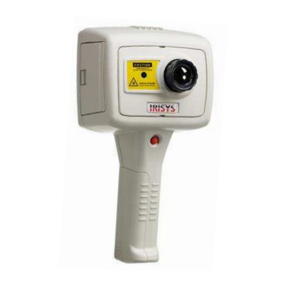
Multi-Purpose Thermal Imager
Safety Warning:
The equipment described in this document uses a Class 2 laser. Under no account should anyone look directly into
the laser beam or the laser beam exit aperture, irreversible damage to the eye may occur. The laser should not be
operated when there are personnel in the imager's field of view.
Caution – use of controls or adjustments or performance of procedures other than those specified in this document
may result in hazardous laser radiation exposure.
Class 2 laser product.
Complies with IEC/EN 60825-1
(2001).
Conforms to USA 21 CFR 1040.10
and 1040.11 except for deviations
pursuant to laser notice No. 50 dated
th
July 26
2001.
© 2006 InfraRed Integrated Systems Ltd. No part of this publication may be reproduced without prior permission in writing from
Infrared Integrated Systems Ltd. This document gives only a general description of the products and except where expressly provided
shall form no part of any contract. From time to time changes may be made in the products.
IRISYS
IRI 4010
User Manual
Page 1 of 29
IPU 40108
InfraRed Integrated Systems Ltd
Park Circle, Tithe Barn Way
Swan Valley
Northampton
NN4 9BG
Tel: (01604) 594 200
Fax: (01604) 594 210
Email:
sales@irisys.co.uk
Advertisement
Table of Contents

Related Manuals for IriSys IRI 4010


Summary of Contents for IriSys IRI 4010
- Page 1 IPU 40108 IRISYS Multi-Purpose Thermal Imager IRI 4010 User Manual Safety Warning: The equipment described in this document uses a Class 2 laser. Under no account should anyone look directly into the laser beam or the laser beam exit aperture, irreversible damage to the eye may occur. The laser should not be operated when there are personnel in the imager’s field of view.
-
Page 2: Table Of Contents
3.4.9.1 Brightness & Contrast Definitions ......................13 ............................15 ECHNICAL 3.5.1 Field Of View ........................... 15 THERMAL IMAGE TRANSFER FROM IRI 4010 TO A PC ............16 SD C ............................16 USB C ............................16 ABLE USING THE IRI 4010 THERMAL IMAGER WITH A PC .............. 17 PC R ........................... -
Page 3: Introduction
This user manual describes the operation of the IRI 4010 multi-purpose infrared thermal imager and its associated software and accessories. 2 Getting Started 2.1 Unpacking After unpacking the IRI 4010 carrying case, you will find the standard items as shown in Figure 1. USB SD Card Reader and Carrying Case... -
Page 4: Powering The Iri 4010
IRI 4010 Thermal Imager. NOTE: • The mains power supply included with the IRI 4010 is for powering the IRI 4010; it will also recharge the battery (see Section 2.2.3). Page 4 of 29... -
Page 5: Battery Charging
The IRI 4010’s battery can be charged in the imager by inserting the included 12V power supply into the DC socket under the cover on the side of the IRI 4010 imager; see Figure 4. It takes approximately 4 hours to fully charge a fully depleted battery if the imager is switched off. Charging the battery with the imager switched on takes longer. -
Page 6: Switching On The Iri 4010
3.3 Information Splash Screen The IRI 4010’s splash screen appears for approximately 20 seconds when the imager is switched on. It displays the time and date so the user can check that any images saved will be recorded with the correct time and date. -
Page 7: Using The Iri 4010 Thermal Imager
IPU 40108 3.4 Using the IRI 4010 Thermal Imager 3.4.1 Focusing If the imager is not focused, the image quality will be poor and temperature measurements will not be accurate. Rotating the lens in a clockwise direction (from front view) focuses the imager at longer distances up to infinity. -
Page 8: Buttons
IPU 40108 3.4.3 Buttons Operation of the IRISYS 4010 imager application is by means of the 4 hot buttons, the 4 directional buttons, the menu button and the laser button (see Figure 10). • The hot buttons are mainly used to give quick control of:... -
Page 9: Iri 4010 Hot Button Operation
3.4.4 IRI 4010 Hot Button Operation This section describes some of the basic functions of the IRI 4010. The IRI 4010’s hot buttons are labelled 1 to 4 from left to right for the purposes of this user manual. Their function is displayed as hot button labels on the IRI 4010’s display. -
Page 10: Directional Buttons
Level and Span Definitions When hot button 4 is set to manual the IRI 4010’s image settings can be manually controlled by adjusting the level and span. When hot button 3 shows L-S, the “right” and “left” buttons respectively will increase and decrease the span of the image (4˚C in the example in Figure 14). -
Page 11: Menu Operation And Functions
IPU 40108 3.4.7 Menu Operation and Functions The main menu structure is opened by pressing the menu button in the centre of the directional buttons. Figure 15: Menu Button There are four sub-menus, which contain the functions listed in Table 1. Measurement Settings Camera Settings Image Browser... -
Page 12: Camera Settings
Factory Settings – For the convenience of the user, many settings are persistent, i.e. the settings and values are remembered when the IRI 4010 is switched off. Selecting the factory settings function restores the imager to its factory default settings. -
Page 13: Using The Laser Pointer
IPU 40108 3.4.8 Using the Laser Pointer When the IRI 4010 is switched ‘ON’, the laser may be activated by pressing and holding down the red laser button. Laser Button The laser pointer is used to illuminate and identify features in the image. The laser pointer illuminates the area of the scene that coincides with the green circle indicator on the display –... - Page 14 IPU 40108 Edit the Contrast Edit the Brightness Default contrast Default brightness Increasing the contrast uses more of the outer colours Increasing the thermal brightness uses more of the of the colour palette i.e. black and white in the upper half of the colour bar. rainbow example.
-
Page 15: Technical
IPU 40108 3.5 Technical 3.5.1 Field Of View The IRI 4010 has a 20˚ x 15˚ Field of View, and a 160 x 120 (19200) pixel detector. Figure 20: Field of View 160 pixels 120 pixels Figure 21: 19200 Pixel Array ... -
Page 16: Thermal Image Transfer From Iri 4010 To A Pc
4.1 SD Card The Secure Digital (SD) memory card is the IRI 4010’s storage device for thermal images. This is also used to transfer thermal images to a PC when used with the SD card reader. Note that the imager will not be able to save thermal images without the SD card installed. -
Page 17: Using The Iri 4010 Thermal Imager With A Pc
SD card reader. The “IRISYS 4000 Series Imager” application can be used for analysis of images previously saved onto an IRI 4010 SD card, or for downloading a live thermal image from the IRI 4010 via a USB cable. 5.2 Installation of Software onto PC The software is supplied on a mini CD-Rom. -
Page 18: Menus And Toolbar
IPU 40108 Figure 26: Application Window 5.3.1 Menus and Toolbar The menu includes familiar Windows menu items such as “File”, “Edit”, “View”, Tools” and “Help”. Figure 27: The Menu 5.3.1.1 Menus 5.3.1.1.1 File The File menu contains the following features: •... - Page 19 IPU 40108 Figure 28: Windows Explorer The iri files can be previewed in any of the five Windows explorer views: thumbnail, tile, icon, list or details, by selecting the “View” button in Windows explorer (shown in Figures 28 and 29). Figure 29: View Selector After an image has been opened, the application window looks similar to figure 30 below.
- Page 20 Microsoft Excel and other spreadsheet applications. 6) Recent Files – a list of recently opened iri files appears here for easy selection. 7) Exit – closes the IRISYS 4000 Series Imager application. 5.3.1.1.2 Edit The Edit menu contains the following features: •...
- Page 21 IPU 40108 Measurement Cursor List - This toggles the display of the measurement cursors list shown in Figure 33, which includes the spot measurement, pixel position, and the difference between measurement cursors 1 and 2. It also displays the hottest and coldest measurements in the scene, their difference, and the average temperature for the image.
- Page 22 IPU 40108 Area Select – This toggles a rectangular area over the centre of the image. The maximum, minimum and average temperatures for this area are then displayed in the measurement cursors list, allowing measurement by area analysis. The area’s position can be moved in conjunction with the zoom & pan control (see Figure 36).
- Page 23 IPU 40108 Profiles – This toggles the 2D profile view which is used to display a graphical representation of the temperature values along the selected vertical and horizontal lines. Intensity Plot Lines Cross Sections Thermal Intensity Plots Figure 38: 2D Profiles To the left of the image is a thermal intensity plot which corresponds to the vertical cross section through the image.
- Page 24 IPU 40108 Figure 40: Display Tab In the Display tab, it is possible to: • Adjust the span of the image manually (by typing) • Adjust the span of the image automatically • Select one of four colour palettes • Select whether to display the image at its original resolution or to interpolate the image to 320 x 240 or 640 x 480 •...
- Page 25 IPU 40108 The Settings tab is shown below: Figure 42: Settings Tab In the Settings tab, it is possible to: • Select ˚C, ˚F or K • Adjust the reflected temperature correction • Adjust the target object emissivity • Adjust the required capture time and date •...
- Page 26 Capture from imager… - After setting up the Imager Comms Config, select this to take a new image from the imager. The IRI 4010 imager must be switched on and connected via the USB cable provided to a USB port on your computer. The file transfer takes approximately 10 seconds. As always when taking an image, make sure the imager is correctly focused on the target.
-
Page 27: Toolbar
Help The Help menu gives the following information: • About 1) About IRISYS 4000 Series Imager – This displays the IRISYS software version being used. Figure 46: Version Information 5.3.1.2 Toolbar The Toolbar includes 12 icons; all of which have been covered in the menus. The icons are listed below. -
Page 28: Emissivity Lookup Table
IPU 40108 6 Emissivity Lookup Table Below is a list of approximate emissivity values for a range of materials for making more accurate temperature measurements. NOTE: Emissivity values often vary with temperature and wavelength so this table is included as a guide only. -
Page 29: Customer Feedback
If you have had any technical issues or feedback with regard to your IRI 4010 Multi-Purpose Thermal Imager, please complete the details below and send it back to IRISYS at the address on the front page of this manual. Name:...
Need help?
Do you have a question about the IRI 4010 and is the answer not in the manual?
Questions and answers