Table of Contents
Advertisement
Quick Links
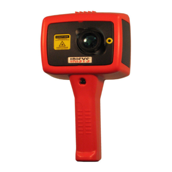
Universal Thermal Imager
Safety Warning.
The equipment described in this document uses a Class 2 laser. Under no account should anyone look
directly into the laser beam or the laser beam exit aperture, irreversible damage to the eye may occur. The
laser should not be operated when there are personnel in the imager's field of view.
Caution – use of controls or adjustments or performance of procedures other than those specified in this
document may result in hazardous laser radiation exposure.
© 2007 InfraRed Integrated Systems Ltd. No part of this publication may be reproduced without prior permission in writing from
Infrared Integrated Systems Ltd. This document gives only a general description of the products and except where expressly
provided shall form no part of any contract. From time to time changes may be made in the products.
IRISYS
Type IRI 1020
User Manual
1 of 16
IPU 40151 Issue 1
InfraRed Integrated Systems Ltd.
Park Circle, Tithe Barn Way
Swan Valley
Northampton
NN4 9BG
United Kingdom
Tel +44 (0) 1604 594 200
Fax +44 (0) 1604 594 210
Email:
sales@irisys.co.uk
Website:
www.irisys.co.uk
Advertisement
Table of Contents

Subscribe to Our Youtube Channel
Related Manuals for IriSys IRI 1020


Summary of Contents for IriSys IRI 1020
- Page 1 IPU 40151 Issue 1 IRISYS Universal Thermal Imager Type IRI 1020 User Manual Safety Warning. The equipment described in this document uses a Class 2 laser. Under no account should anyone look directly into the laser beam or the laser beam exit aperture, irreversible damage to the eye may occur. The laser should not be operated when there are personnel in the imager’s field of view.
-
Page 2: Table Of Contents
3.0 IMAGE ADJUSTMENT ……………………………………………………………… …………...………………………..9 4.0 USER SETTINGS…………..……………………………………………… ……………………...…………………………...9 5.0 USING THE LASER POINTER………………………………………………………………….. ………………………….10 6.0 THERMAL IMAGE TRANSFER FROM IRI 1020 TO A PC……… …………………………………..………… ………...10 7.0 INSTALLING SOFTWARE ON A PC……………………………………………………… ………………..……………...11 7.1 OPERATING IRI 1020 IMAGER SOFTWARE………………………………………………… ……………...……………11 7.2 USING THE IRI 1020 THERMAL IMAGER WITH A PC ……………………………………………... -
Page 3: Getting Started
Wrist strap, Tool box, 1.2 Unpacking After unpacking the IRI 1020 toolbox, as seen in figure 1, inspect all the items. If any item is damaged or missing, notify your dealer immediately. Figure 1. Imager toolbox. 1.3 Powering the IRI 1020 The IRI 1020 Thermal Imager operates from either the rechargeable battery pack or from AC mains power. -
Page 4: Battery Recharge Time
The IRI 1020’s battery can be charged in the imager by inserting the included 12V power supply into the DC socket under the door on the side of the IRI 1020 imager, as seen in figure 4. It takes approximately 6 hours to fully charge a fully depleted battery if the imager is switched off. Charging the battery with the imager switched on takes longer. -
Page 5: Operating
Practical use of the IRI 1020 is detailed in this section. 2.1 Hardware The IRI 1020 is designed for use as a handheld thermal imager. Thermal images stored on the supplied memory card, can be transferred to a PC or laptop computer using the memory card reader. PC software is for viewing and analysis of saved thermal images. -
Page 6: Screen Display Items
IPU 40151 Issue 1 2.3 Screen Display Items. Battery life Figure 7. Screen Display Items. Indicator Temperature measurement cursors and their temperature measurement values, Temperature scale and their temperature with the maximum difference value ( ). and minimum values of the span When hotkey 2 is not selected, the emissivity value and reflected... -
Page 7: Buttons
2.5 Buttons Operation of the IRISYS 1020 imager is by means of the 4 hotkey buttons, hotkey 1 to hotkey 4, the 4 directional arrow buttons, the centre button and the laser button. The hotkey buttons are mainly used to give control of the following functions. -
Page 8: Hotkey Buttons
Centre button. 2.7 Hotkey Buttons Below are the icons as they appear on the IRI 1020 display. Hotkey 1, Pressing hotkey 1 toggles between the following options:- E is for the setting of Emissivity and the value can be adjusted by using the up, down, left and right, directional arrow keys. -
Page 9: Image Adjustment
Span In Span out Maximum Span Minimum Span 4.0 User settings. User settings – For the convenience of the user, many settings are persistent, the settings and values are remembered when the IRI 1020 is switched off. 9 of 16... -
Page 10: Using The Laser Pointer
IPU 40151 Issue 1 5.0 Using the Laser pointer. When the IRI 1020 is switched ‘ON’, the laser may be activated by pressing and holding down the laser button. Figure 11. Laser pointer. Laser The laser pointer, as seen in figure 11, is used to illuminate and identify features in the image. -
Page 11: Installing Software On A Pc
Follow the on screen prompts to complete the installation. NOTE: • The IRISYS 1020 Imager software will by default be installed into the following path: C:\Program Files\IRISYS\IRISYS 1000 Series Imager • The above path and name can be changed during the installation, but it is advisable to leave it as the default. -
Page 12: Thermal Imager Launch Window
IPU 40151 Issue 1 Figure 13. PC launch window. Control Panel 7.3 Thermal Imager Launch Window. Adjusting the displayed Thermal Image: • The sensitivity and range can be automatically adjusted for a single image by clicking on the ‘Single Auto Gain’ button. The ‘Sensitivity’... -
Page 13: Edit
IPU 40151 Issue 1 7.6 The Edit menu allows the following. Copy (Ctrl C) – takes a copy of the image, it can then be pasted into another document • e.g. MS Word. Copy to Bitmap – takes a snapshot of the image and saves it as a bitmap image. •... -
Page 14: Operating Notes And Precautions. Temperature Measurement
9.1 The lens and associated holder is not user adjustable. The focal point of the imager has been set at manufacture according to specification. IRISYS will not be held responsible for any internal damage should this mount be altered. Behind the lens is the accurately positioned chopper blade. -
Page 15: Customer Feedback
9.3 Customer Feedback. If you have had any technical issues or feedback with regard to your IRI 1020 Thermal Imager, please complete the details below and send it back to IRISYS at the address on the front page of this manual. Name:...
Need help?
Do you have a question about the IRI 1020 and is the answer not in the manual?
Questions and answers