
Subscribe to Our Youtube Channel
Related Manuals for Ariens IKON X 42


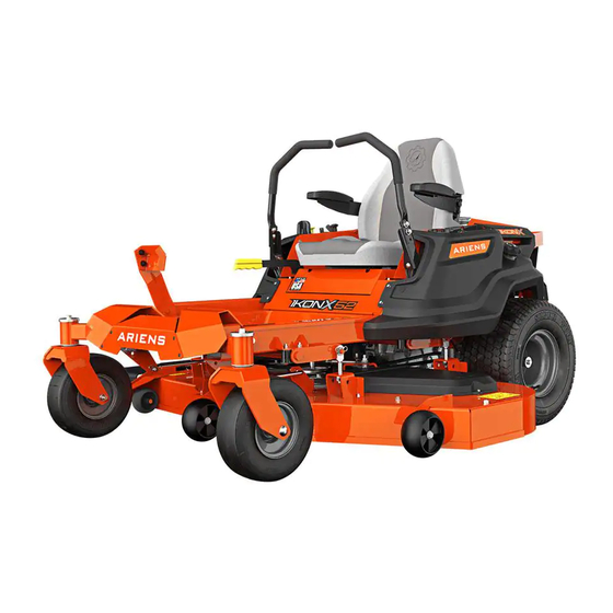
Summary of Contents for Ariens IKON X 42
- Page 1 IKON X Operator’s Manual Manuel du Utilisateur Models 915175 – IKON X 42 (SN 000101 +) 915177 – IKON X 52 (SN 000101 +) 915179 – IKON X 42 CARB (SN 000101 +) ENGLISH • 04814400B 6/15 FRANÇAIS Printed in USA...
-
Page 2: Table Of Contents
TABLE OF CONTENTS WELCOME ..... . 1 Check Engine Oil ....19 Check Tire Pressure . -
Page 3: Welcome
WELCOME Congratulations on your purchase and welcome to the Ariens family! Every machine in the Ariens lineup is designed for long-lasting and unsurpassed performance. We are confident your machine will be part of your family for many years to come. -
Page 4: Safety
1. Danger SAFETY DANGER: Indicates an Read these safety rules and follow them IMMINENTLY HAZARDOUS closely. Failure to follow these rules could SITUATION! If not avoided, WILL RESULT in death or lead to loss of control of unit, severe personal serious injury. - Page 5 Safety Decal Locations 07800536 KEEP HANDS and FEET AWAY 07800537 Figure 2 Safety Decal Descriptions 1. DANGER! 2. DANGER! Discharge Hazard - Discharge Hazard - NEVER NEVER operate unit direct discharge toward without discharge chute in people, pets or property. operating position.
- Page 6 3.2 Discharge Hazard Keep children and others Discharge Hazard - NEVER away from unit while unit is direct discharge toward in operation. people, pets or property. Thrown objects can cause injury or damage. Keep feet and hands away from all rotating or moving DO NOT operate mower parts.
- Page 7 3.5 Bystander Hazard 5. HOT PARTS! DO NOT touch parts which DO NOT operate the unit in are hot from operation. the presence of bystanders. ALWAYS allow parts to cool. 6. ROTATING PARTS! DO NOT carry passengers. AVOID INJURY. Stay clear of rotating parts.
-
Page 8: Safety Rules
SAFETY RULES Children The following safety instructions are based Tragic accidents can occur if the operator is on the B71.1 specifications of the American not alert to the presence of children. National Standards Institute in effect at the Children are often attracted to the machine time of production. - Page 9 Inspect unit before each use for missing or NEVER direct discharged material toward damaged decals and shields, correctly anyone. Avoid discharging material against operating safety interlock system, and a wall or obstruction. Material may ricochet deterioration of grass catchers. Replace or back toward the operator.
- Page 10 Use care when approaching blind corners, Choose a low ground speed so you will not shrubs, trees or other objects that may have to stop or shift while on a slope. obscure vision. DO NOT mow near drop-offs, ditches, or Dust, smoke, fog, etc.
- Page 11 (except where when necessary. specifically recommended). Stop engine, Use only Ariens Company-recommended remove key and spark plug wire and wait for attachments that are appropriate to your use all moving parts to stop before servicing or and can be used safely in your application.
- Page 12 Transporting Unit Use extra care when loading or unloading the machine into a trailer or truck. Secure unit chassis to transport vehicle. NEVER secure from rods or linkages that could be damaged. DO NOT transport machine while engine is running. ALWAYS turn off power to attachment and shut off fuel when transporting unit.
-
Page 13: Assembly
ASSEMBLY REQUIRED TOOLS • Adjustable wrench • Petroleum jelly or dielectric grease UNPACK UNIT 1. Disengage transmission. See Move Unit Manually on page 18. 2. Move unit from container to a level surface. 3. Remove all other pieces from shipping container. -
Page 14: Secure Operator Presence Cable
2. Remove nut from bolt on battery tray. INSTALL ARM RESTS Retain nut. See Figure 5. (IF NEEDED) 3. Tilt seat up slightly so cable end reaches See Figure 7. bolt on battery tray. 1. Remove one bolt, nut and washer from 4. -
Page 15: Install Deck Lift Pedal
INSTALL DECK LIFT PEDAL PREPARE UNIT FOR OPERATION See Figure 8. 1. Connect battery. See Install Battery on page 22. 1. Remove hardware securing deck lift pedal to unit and remove pedal. 2. Adjust seat to a comfortable position. See Adjust Seat on page 26. -
Page 16: Controls And Features
CONTROLS AND FEATURES Figure 10 1. Fuel Tank and Cap 13. Seat Adjustment Lever 2. Fuel Level Window 14. Parking Brake Lever 3. Oil Filter 15. Belt Guard (2) 4. Oil Drain 16. Mower Deck 5. Engine Oil Dipstick 17. Steering Lever 6. -
Page 17: Ignition Key
POWER-TAKE-OFF (PTO) KNOB WARNING: AVOID INJURY. See Figure 14. Read and understand the Controls power to mower blades. The engine entire Safety section before will not start with the PTO knob in the on proceeding. position. IGNITION KEY WARNING: AVOID INJURY. See Figure 11. -
Page 18: Safety Interlock System
SAFETY INTERLOCK SYSTEM 4. Check function of the Safety Interlock System by performing the tests below. Monitors the interaction of various unit Contact your Ariens dealer for repair if features for operator safety. any of the tests fail. STEERING LEVERS... -
Page 19: Start The Engine
START THE ENGINE Direction Lever Position of Travel 1. Push PTO knob down to off position. Left Turn Push right lever 2. Move steering levers to neutral position. farther forward 3. Set parking brake. than the left lever. 4. If engine is cold, pull choke knob up to on position. -
Page 20: Move Unit Manually
• * Refer to engine manual for instructions. + Use tubing included in literature pack to drain engine oil. SERVICE PARTS See your Ariens dealer to purchase service Figure 17 parts for your unit. TRANSPORT UNIT Description Qty. Part No. -
Page 21: Hour Meter
Check function of the Safety Interlock System chuck and extension hose by performing the tests below. Contact your long enough to allow you to Ariens dealer for repair if any of the tests fail. stand to one side. Test Steering PTO Parking Result •... -
Page 22: Check Fasteners
CHECK FASTENERS MAINTENANCE PREPARATION Check for loose hardware. Before starting any of the following maintenance procedures: LUBRICATE UNIT 1. Park unit a flat, level surface. See Figure 19. 2. Move steering levers to neutral position. 1. Apply grease to grease zerk on each front 3. -
Page 23: Check Battery
1. Unsharpened Cutting Edge 2. Sharpened Cutting Edge 3. 0 – 1.3 cm (0 – 1/2") Recession 1. Spindle 4. Air Lift Erosion Area 2. Mower Blade 3. Washer Figure 23 4. Nut Figure 22 CAUTION: Unbalanced blades cause excessive vibration and Sharpen Blades eventual damage to unit. - Page 24 Remove Battery Install Battery 1. Tip seat forward. See Figure 24. Install Factory Battery See Figure 25. 1. Position battery in battery tray. 2. Align upper hole in hold-down bracket over the 1/4 x 3/4" bolt. Position bracket as shown in Figure 25. 3.
- Page 25 4. Insert hole in L bracket over bolt as information about charging. shown in Figure 28 and secure with one IMPORTANT: Ariens does not recommend hex nut. jump starting your unit. Jump-starting can 5. Insert 1/4 x 1/2" bolt though holes in damage engine and system components.
-
Page 26: Check Mower Belts
CHECK MOWER BELTS Install Deck Drive Belt 1. Install deck drive belt. See Figure 30. Check belts for wear and replace as needed. NOTICE: Belt will not have tension until Remove Deck Drive Belt routed around drive pulley and idler arm is reinstalled. - Page 27 3. Loosen nut on eye bolt and disconnect 6. Disconnect clutch wire. idler arm spring. See Figure 31. 7. Remove ground drive belt. NOTICE: Route the belt over the top of the pulleys for easiest removal. Install Ground Drive Belt 1.
-
Page 28: Adjustments
ADJUSTMENTS WARNING: AVOID INJURY. Read and understand the Safety section before proceeding. ADJUST SEAT See Figure 34. 1. Pull seat adjustment lever up to unlock seat. 2. Move seat to desired position. 3. Release seat adjustment lever to lock 1. Adjusting Hole seat in place. -
Page 29: Adjust Unit To Track Straight
STRAIGHT ADJUST PARKING BRAKE NOTICE: Reverse travel can only be LEVER adjusted by your Ariens dealer. 1. Park unit a flat, level surface and chock Check Tire Pressure wheels so unit cannot roll. 1. Check pressure of both tires. If needed, 2. -
Page 30: Remove And Install Mower Deck
1. Self-tapping Screws 2. Belt Cover 3. Idler Spring 4. Spring Bracket 1. Upper Jam Nut Figure 40 2. Lower Jam Nut Figure 39 6. Remove one hairpin from drag link to disconnect drag link from mower deck REMOVE AND INSTALL MOWER bracket. -
Page 31: Adjust Mower Deck
8. Remove one flange nut, one hex bolt, one flat steel washer and two sleeve bushings from deck lift lever. Retain hardware. See Figure 42. 1. Deck Lift Lever 2. Deck Link 3. 3/8 x 1/2 x 1" (Longer) Sleeve Bushing 1. -
Page 32: Storage
Level Mower Deck Set Blade Pitch Pitch is the difference in blade height from IMPORTANT: Make sure unit is on a flat, front to back. level surface and that tires are inflated to the recommended pressure. See Specifications IMPORTANT: Level the mower deck before on page 34. -
Page 33: Long-Term Storage
2. Charge and install the battery. ACCESSORIES See your Ariens dealer for a complete list of compatible accessories and attachments for your unit. Description Part No. -
Page 34: Troubleshooting
Connect spark plug wire(s) or replace spark plug(s) are faulty. spark plug(s). Refer to engine manual. Electrical system is faulty. Contact your Ariens dealer. Engine is faulty. Contact your Ariens dealer. Choke control knob is in on Move knob to off position. - Page 35 TROUBLESHOOTING Problem Probable Cause Correction Mower blades not level or mower Level and adjust pitch of mower deck. deck pitch is incorrect. See Adjust Mower Deck on page 29. Mower blades are dull or faulty. Sharpen or replace mower blades. See Sharpen Blades on page 21.
-
Page 36: Specifications
SPECIFICATIONS Model Number 915175 915177 915179 Model IKON X 42 IKON X 52 IKON X 42 CARB Engine Kohler 7000 Series 725.0 (44.2) Engine Displacement – cm Governed RPM (May be different from 3300 maximum RPM) Oil Capacity Refer to Engine Manual Drive Forward Maximum –... -
Page 37: Warranty
Register the product immediately at the time of sale. If the dealer does not register the product, the customer must complete the product registration card in the literature package and return it to the Ariens Company, or register the unit online at www.ariens.com, www.gravely.com, www.countax.com. - Page 38 Exclusions – Items Not Covered by This Warranty • Parts that are not genuine Ariens, Gravely or Countax service parts are not covered by this warranty and may void the warranty. • Damages resulting from the installation or use of any part, accessory, or attachment which is not approved by the Ariens Company for use with product(s) identified herein are not covered by this war- ranty.
- Page 40 655 West Ryan Street Brillion, WI 54110 ariensco.com ariens.com...
Need help?
Do you have a question about the IKON X 42 and is the answer not in the manual?
Questions and answers