Table of Contents
Advertisement
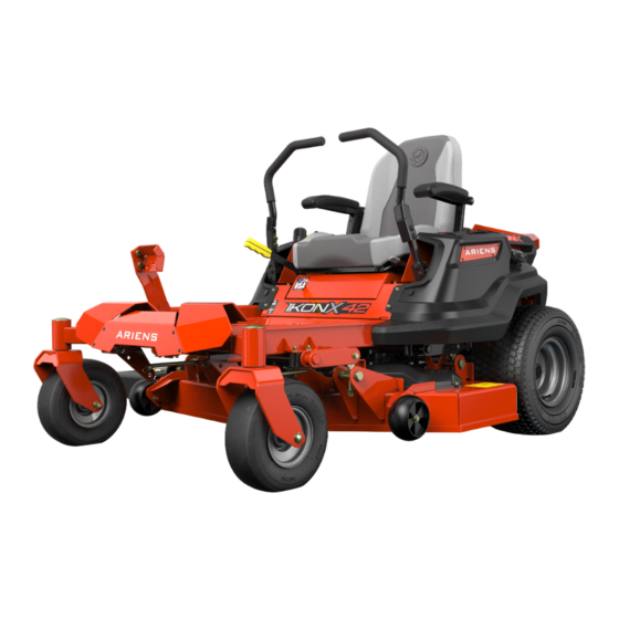
915220 – IKON-X 42
(SN 030000 +)
915221 – IKON-X 42
(SN 030000 +)
915222 – IKON-X 52
(SN 030000 +)
915223 – IKON-X 52
(SN 030000 +)
915224 – IKON-X 42 CARB
(SN 030000 +)
915225 – IKON-X 52 CARB
(SN 030000 +)
915226 – IKON-XL 42
(SN 030000 +)
915227 – IKON-XL 52
(SN 030000 +)
915228 – IKON-XL 60
(SN 030000 +)
915229 – IKON-XL 60
(SN 030000 +)
E10
Models
ENGLISH
FRANÇAIS
IKON-X
IKON-XL
Operator's Manual
Manuel du Utilisateur
915237 – IKON-XL 42 CARB
(SN 030000 +)
915239 – IKON-XL 52 CARB
(SN 030000 +)
915241 – IKON-XL 60 CARB
(SN 030000 +)
™
™
•
05167900
8/17
Printed in USA
Advertisement
Table of Contents

Related Manuals for Ariens IKON-X


Summary of Contents for Ariens IKON-X
- Page 1 915241 – IKON-XL 60 CARB (SN 030000 +) (SN 030000 +) 915223 – IKON-X 52 (SN 030000 +) 915224 – IKON-X 42 CARB (SN 030000 +) 915225 – IKON-X 52 CARB (SN 030000 +) 915226 – IKON-XL 42 (SN 030000 +) 915227 –...
-
Page 2: Table Of Contents
TABLE OF CONTENTS WELCOME ..... . 1 MAINTENANCE ....17 Maintenance Schedule . -
Page 3: Welcome
WELCOME Congratulations on your purchase and welcome to the Ariens family! Every machine in the Ariens lineup is designed for long-lasting and unsurpassed performance. We are confident your machine will be part of your family for many years to come. -
Page 4: Safety
The safety alert symbol above and signal penalties. Emission controls and components words below are used on decals and in this can only be adjusted by an Ariens Company manual. Read and understand all safety dealer or an authorized engine messages. -
Page 5: Safety Decals
5. Important ALWAYS replace missing or damaged safety decals. Replacement decal part numbers are IMPORTANT: Indicates general reference found in the parts manual for your machine information worthy of special attention. and may be ordered from your dealer. SAFETY DECALS See Figure 2 for safety decal locations. - Page 6 Shut off engine, remove key, and read manual before Keep all guards and shields servicing or making in place. adjustments to unit. 3.2 Discharge Hazard Keep children and others Discharge Hazard - NEVER away from unit while unit is direct discharge toward in operation.
- Page 7 5. HOT PARTS! Remove key and disconnect spark plug before servicing or making adjustments to DO NOT touch parts which unit. are hot from operation. ALWAYS allow parts to cool. 3.5 Bystander Hazard 6. ROTATING PARTS! DO NOT operate the unit in the presence of bystanders.
-
Page 8: Safety Rules
SAFETY RULES Children The following safety instructions are based Tragic accidents can occur if the operator is on the B71.1 specifications of the American not alert to the presence of children. National Standards Institute and ISO 5395 in Children are often attracted to the machine effect at the time of production. - Page 9 Inspect unit before each use for missing or NEVER direct discharged material toward damaged decals and shields, correctly anyone. Avoid discharging material against operating safety interlock system, and a wall or obstruction. Material may ricochet deterioration of grass catchers. Replace or back toward the operator.
- Page 10 Check for weak spots on docks, ramps or DO NOT park on slopes unless necessary. floors. Avoid uneven work areas and rough When parking on slope ALWAYS chock or terrain. Stay alert for hidden hazards or block wheels. ALWAYS set parking brake. traffic.
- Page 11 Stop engine, when necessary. remove key and spark plug wire and wait for all moving parts to stop before servicing or Use only Ariens Company-recommended cleaning. attachments that are appropriate to your use and can be used safely in your application.
- Page 12 Transporting Unit Use extra care when loading or unloading the machine into a trailer or truck. Secure unit chassis to transport vehicle. NEVER secure from rods or linkages that could be damaged. DO NOT transport machine while engine is running. ALWAYS turn off power to attachment and shut off fuel when transporting unit.
-
Page 13: Controls And Features
CONTROLS AND FEATURES Models 915220, 915222, 915224, 915226, 915227, 915228, 915237, 915239 Models 915221, 915223, 915225, 915229, 915241 Figure 3 EN - 11... - Page 14 1. Fuel Tank and Cap 13. Parking Brake Lever 2. Oil Filter 14. Belt Guard (2) 3. Oil Drain 15. Mower Deck 4. Engine Oil Dipstick 16. Steering Lever (2) 5. Ignition Key 17. Discharge Chute 6. Choke Control Knob 18.
-
Page 15: Ignition Key
THROTTLE CONTROL LEVER WARNING: AVOID INJURY. See Figure 6. Read and understand the Controls engine speed. entire Safety section before proceeding. See Figure 3 for all controls and features locations. Fast IGNITION KEY See Figure 4. Controls power to the engine. The key cannot be removed when in run position. -
Page 16: Parking Brake Lever
System by performing the tests in Check features for operator safety. Safety Interlock System on page 21. STEERING LEVERS Contact your Ariens dealer for repair if any of the tests fail. Control the direction and speed of unit. The 5. Set cutting height. See Figure 9. -
Page 17: Start The Engine
OPERATE UNIT 1. Release parking brake. WARNING: AVOID INJURY. Move the steering levers slowly and keep the throttle at slow speed until you learn how to operate the unit. 2. Set throttle to slow speed. 3. Pull PTO knob up to on position. IMPORTANT: Never engage the PTO if the mower is plugged with grass or other material. -
Page 18: Stop The Engine
For Best Mowing Results Models 915226, 915227, 915228, 915229, • Cut grass when it is dry. 915237, 915239, 915241 • Keep mower blades sharp. • Keep mower deck properly leveled. Rear Position • Do not set height of cut too low. For very tall grass, mow twice. -
Page 19: Transport Unit
TRANSPORT UNIT SERVICE PARTS 1. Stop engine, set parking brake and See your Ariens dealer to purchase service remove key from ignition. parts for your unit. 2. Secure unit chassis to transport vehicle. Common Service Parts NOTICE: NEVER secure from rods or Description Qty. - Page 20 Model 915222 Description Qty. Part No. Oil Filter 21397200 Description Qty. Part No. Air Filter 21555500 Transaxle Drive Belt 07200718 Mower Belt 07200023 Model 915225 Mower Blade 04771200 Front Wheel and Tire 07101127 Description Qty. Part No. Assembly Transaxle Drive Belt 07200718 Drive Wheel and Tire 07101130...
- Page 21 Model 915227 Model 915229 Description Qty. Part No. Description Qty. Part No. Transaxle Drive Belt 07200724 Transaxle Drive Belt 07200724 Mower Belt 07200023 Mower Belt 07200804 Mower Blade 04771200 Mower Blade 04965000 Front Wheel and Tire 07101105 Front Wheel and Tire 07101105 Assembly Assembly...
-
Page 22: Service Position
Model 915239 SERVICE POSITION See Figure 12. Description Qty. Part No. Before starting any of the following Transaxle Drive Belt 07200724 maintenance procedures: Mower Belt 07200023 1. Park unit a flat, level surface. Mower Blade 04771200 2. Stop engine, remove key and wait for all Front Wheel and Tire 07101105 moving parts to stop and for hot parts to... -
Page 23: Check Safety Interlock System
See Specifications on page 38 for recommended tire pressure. Check function of the Safety Interlock System by performing the tests below. Contact your Ariens dealer for repair if any of the tests fail. WARNING: AVOID INJURY. Explosive separation of tire Test Steering... -
Page 24: Lubricate Unit
LUBRICATE UNIT Models 915226, 915227, 915228, 915229, 915237, 915239, 915241 See Figure 14. 1. Place unit in service position. See Service Position on page 20. 2. Apply grease to seat tracks through slots under seat plate. 1. Spindle 2. Mower Blade 3. -
Page 25: Check Battery
CHECK BATTERY WARNING: Battery posts, terminals and related accessories contain lead and lead compounds, chemicals known to the State of California to cause cancer and reproductive harm. Wash hands after handling. Remove Battery 1. Place unit in service position. See Service Position on page 20. - Page 26 1. Remove hardware retaining L-bracket to Install U1 Battery battery bracket and reinstall hardware 1. Remove factory battery. See Remove into L-bracket hole nearest curved edge. Battery on page 23. See Figure 18. 2. Remove hardware from L-bracket and secure L-bracket to battery bracket. See Figure 20.
-
Page 27: Check Mower Belts
IMPORTANT: Always follow information provided on battery by battery manufacturer. Contact battery manufacturer for detailed information about charging. IMPORTANT: Ariens does not recommend 1. Spring jump starting your unit. Jump-starting can 2. Belt Cover damage engine and system components. - Page 28 Install Deck Drive Belt Remove Ground Drive Belt 1. Install deck drive belt. See Figure 24. IMPORTANT: Retain all parts for reinstallation. IMPORTANT: Belt will not have tension until routed around drive pulley and idler arm is 1. Place unit in service position. See reinstalled.
-
Page 29: Hydraulic Oil
1. Install ground drive belt. See Figure 28. 2. Remove the cap from the expansion tank. 3. Fill the expansion tank with 15W-50 synthetic motor oil (Ariens p/n 00057100) or equivalent until oil level reaches the cold fill line on the tank. - Page 30 75 hours of operation and then every 400 hours. Use 15W-50 synthetic 10. Add 15W-50 synthetic motor oil (Gravely motor oil (Ariens p/n 00057100) or p/n 00057100) or equivalent until oil equivalent. appears at the bottom of the vent port (1892.7 mL (64 fl.
-
Page 31: Adjustments
2. Disengage the parking brake and put the Models 915220, 915221, 915222, 915223, transaxle bypass levers in the neutral 915224, 915225 position (see Move Unit Manually on See Figure 32. page 16). 1. Tip seat forward. 3. Start the engine and slowly move the 2. -
Page 32: Adjust Unit To Track Straight
8. Tighten nut. ADJUST UNIT TO TRACK STRAIGHT NOTICE: Reverse travel can only be adjusted by your Ariens dealer. Check Tire Pressure 1. Check pressure of both tires. See Specifications on page 38 for recommended tire pressure. -
Page 33: Adjust Parking Brake Lever
Adjust Steering Levers See Figure 36. If adjusting tire pressure did not correct tracking problem: 1. Loosen jam nut on adjustment bolt of steering lever that needs adjustment. 2. Adjust drive wheel speed. • Turn adjustment bolt counterclockwise to increase steering lever travel and drive wheel speed. - Page 34 5. Remove deck drive belt from rear drive 8. Remove one flange nut, one hex bolt, one pulley. See Figure 39. flat steel washer and two sleeve bushings from deck lift lever. Retain hardware. See Figure 41. Figure 39 See Figure 40. 6.
-
Page 35: Adjust Mower Deck
1. Set deck to highest cutting height. 2. Position mower blades so blade ends point left to right across the width of the deck. 3. On both sides of the unit, measure the distance to the ground at the cutting edge of the blade. - Page 36 Set Blade Pitch Pitch is the difference in blade height from front to back. IMPORTANT: Level the mower deck before setting blade pitch. 1. Set deck to highest cutting height. 2. Position mower blades so blade ends point front to back. 3.
-
Page 37: Troubleshooting
Connect spark plug wire(s) or replace spark plug(s) are faulty. spark plug(s). Refer to engine manual. Electrical system is faulty. Contact your Ariens dealer. Engine is faulty. Contact your Ariens dealer. Choke control knob is in on Move knob to off position. - Page 38 TROUBLESHOOTING Problem Probable Cause Correction Mower blades not level or mower Level and adjust pitch of mower deck. deck pitch is incorrect. See Adjust Mower Deck on page 33. Mower blades are dull or faulty. Sharpen or replace mower blades. See Sharpen Blades on page 22.
-
Page 39: Storage
STORAGE ACCESSORIES SHORT-TERM STORAGE See your Ariens dealer for a complete list of compatible accessories and attachments for IMPORTANT: NEVER wash unit with high- your unit. pressure water or store outdoors. Description Part No. 1. Allow unit to cool and clean with mild soap and water. -
Page 40: Specifications
SPECIFICATIONS Model Number 915220 915221 915222 915223 Model IKON X 42 IKON X 42 IKON X 52 IKON X 52 Engine Kohler 7000 Kawasaki FR Kohler 7000 Kawasaki FR Series Series Engine Displacement – cm 725.0 (44.2) 726.0 (44.3) 725.0 (44.2) 726.0 (44.3) Maximum RPM –... - Page 41 SPECIFICATIONS Model Number 915224 915225 915226 Model IKON X 42 CARB IKON X 52 CARB IKON XL 42 Engine Kohler 7000 Series Engine Displacement – cm 725.0 (44.2) Maximum RPM – No Load 3300 ± 75 Oil Capacity Refer to Engine Manual Drive Forward Maximum –...
- Page 42 SPECIFICATIONS Model Number 915227 915228 915229 Model IKON XL 52 IKON XL 60 IKON XL 60 Engine Kohler 7000 Series Kawasaki FR 725.0 (44.2) 726.0 (44.3) Engine Displacement – cm Maximum RPM – No Load 3300 ± 75 3300 ± 100 Oil Capacity Refer to Engine Manual Drive...
- Page 43 SPECIFICATIONS Model Number 915237 915239 915241 Model IKON-XL 42 IKON-XL 52 IKON-XL 60 CARB CARB CARB Engine Kawasaki FR730V Kohler 7000 Series CARB CARB 725.0 (44.2) 726.0 (44.3) Engine Displacement – cm Maximum RPM – No Load 3300 ± 75 3300 ±...
-
Page 44: Warranty
Register the product immediately at the time of sale. If the dealer does not register the product, the customer must complete the product registration card in the literature package and return it to the Ariens Company, or register the unit online at www.ariens.com, www.gravely.com, www.countax.com. - Page 45 Exclusions – Items Not Covered by This Warranty • Parts that are not genuine Ariens, Gravely or Countax service parts are not covered by this warranty and may void the warranty. • Damages resulting from the installation or use of any part, accessory, or attachment which is not approved by the Ariens Company for use with product(s) identified herein are not covered by this war- ranty.
- Page 46 655 West Ryan Street Brillion, WI 54110 ariensstore.com ariens.custhelp.com parts.ariens.com...
Need help?
Do you have a question about the IKON-X and is the answer not in the manual?
Questions and answers