Sign In
Upload
Download
Table of Contents
Contents
Add to my manuals
Delete from my manuals
Share
URL of this page:
HTML Link:
Bookmark this page
Add
Manual will be automatically added to "My Manuals"
Print this page
×
Bookmark added
×
Added to my manuals
Manuals
Brands
H3C Manuals
Network Router
MSR 30-10
Installation manual
H3C MSR 30-10 Installation Manual
Msr 30 series
Hide thumbs
1
2
3
4
5
Table Of Contents
6
7
8
9
10
11
12
13
14
15
16
17
18
19
20
21
22
23
24
25
26
27
28
29
30
31
32
33
34
35
36
37
38
39
40
41
42
43
44
45
46
47
48
49
50
51
52
53
54
55
56
57
58
59
60
61
62
63
64
65
66
67
68
69
70
71
72
73
74
75
76
77
78
79
80
81
82
83
84
85
86
87
88
89
90
91
92
93
94
95
96
97
98
99
page
of
99
Go
/
99
Contents
Table of Contents
Troubleshooting
Bookmarks
Table of Contents
Installation Guide
Documentation Feedback
Obtaining Documentation
Technical Support
Table of Contents
Overview
Introduction
System Description
Fixed Interfaces
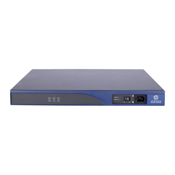
MSR 30-10 Router
MSR 30-11 Router
MSR 30-11E Router
MSR 30-11F Router
MSR 30-16 Router
MSR 30-20 Router
MSR 30-40 Router
MSR 30-60 Router
Slot Arrangement
Generic Modules
SIC/DSIC Cards
MIM/DMIM Cards
Esm
Vpm/Vcpm
Installation Preparations
Requirements on Environment
Requirements on Temperature/Humidity
Requirements on Cleanness
Requirements on Electrostatic Discharge Prevention
Requirements on Electromagnetic Environments
Requirements on Preventing Lightning
Requirements on Workbench
Safety Precautions
Installation Tools, Meters and Equipments
Installation
Installation Process
Installing the Cabinet
Installing the Router
Installing the Router on a Workbench
Installing the Router in a Cabinet
Installing Generic Modules
Connecting the PGND
Connecting the Power Cord
Power Input and PGND
Connecting the AC Power Cord
Connecting the DC Power Cord
Connecting the RPS Power Cord
Connecting the Console Terminal
Fixed Interfaces
Ethernet Interface
Connecting AUX to a Modem
Interface Cards and Interface Modules
Installing and Removing Interface Modules
Slide Rail
Installing a DSIC/DMIM Interface Card
Removing a DSIC/DMIM Interface Card
Installing an XMIM Interface Card
Removing an XMIM Interface Card
Verifying Installation
Startup and Configuration
Startup
Setting up Configuration Environment
Powering on the Router
Startup Process
Configuration Fundamentals
Basic Configuration Procedures
Command Line Interface
Arranging Slots and Numbering Interfaces
Software Maintenance
Introduction
Files
Software Maintenance Methods
Maintaining Application Program and Configuration through Command Lines
Maintaining the Router through TFTP Server
Maintaining the Router through FTP Server
Bootware Menu
Main Bootware Menu
Bootware Submenus
Upgrading an Application Program through an Ethernet Interface
Configuring Ethernet Interface Parameters
Upgrading Procedure
Upgrading Bootware through Ethernet Interface
Upgrading Bootware through Serial Interface
Xmodem Protocol Overview
Modifying Serial Interface Parameters
Upgrading Bootware
Upgrading an Application Program through a Serial Interface
Maintaining Application and Configuration Files
Dealing with Password Loss
User Password Loss
Bootware Password Loss
Super Password Loss
Backing up and Restoring Bootware
Hardware Maintenance
Preparing Tools
Opening/Closing the Chassis Cover
Internal Structure of the Router
Removing/Installing a Power Module
Installing and Removing the Power Module
Installing/Removing a CF Card
Structure
Installing CF Card
Removing CF Card
Replacing a Memory Module
Memory Module Structure
Memory Module Slot
Installing/Removing a Memory Module
Replacing a VPM
VPM Structure
VPM Slot
Installing/Removing a VPM
Installing/Removing an ESM/VCPM Card
Troubleshooting
Troubleshooting the Power System
Troubleshooting the Configuration System
Troubleshooting Application Image Upgrade
Index
Advertisement
Quick Links
1
Msr 30-20 Router
Download this manual
H3C MSR 30 Routers
Installation Guide
Hangzhou H3C Technologies Co., Ltd.
http://www.h3c.com
Document version: T2-08047L-20101217-C-1.05
Table of
Contents
Previous
Page
Next
Page
1
2
3
4
5
Advertisement
Table of Contents
Troubleshooting
Troubleshooting
96
Troubleshooting Application Image Upgrade
97
Need help?
Do you have a question about the MSR 30-10 and is the answer not in the manual?
Ask a question
Questions and answers
Related Manuals for H3C MSR 30-10
Network Router H3C MSR 20-20 Command Reference Manual
Msr 20/30/50 series routers (2742 pages)
Network Router H3C H3C MSR 20 User Manual
Interface card and interface module manual (240 pages)
Network Router H3C H3C MSR 30-20 ROUTER Installation Manual
Msr 30 series (101 pages)
Network Router H3C MSR 30-16 Installation Manual
Msr 30 series routers (97 pages)
Network Router H3C MSR 20-20 User Manual
Msr 20/30/50 series routers (60 pages)
Network Router H3C MSR3600-51F Configuration Manual
Comware 5 ipx (20 pages)
Network Router H3C MSR 30-16 Supplementary Manual
Msr 30 series router telecommunications & certification manual (8 pages)
Network Router H3C MSR Series Configuration Manual
Comware 5 wlan (80 pages)
Network Router H3C MSR 2600 Configuration Manual
Layer 3 (288 pages)
Network Router H3C MSR Series Probe Command Reference
(28 pages)
Network Router H3C MSR Series Command Reference Manual
(37 pages)
Network Router H3C MSR Series Manual
(33 pages)
Network Router H3C MSR 30-40 Installation Manual
Msr 30 series (99 pages)
Network Router H3C MSR Series Troubleshooting Manual
(28 pages)
Network Router H3C MSR 810 Command Reference Manual
(53 pages)
Network Router H3C MSR3600-28-X1 Quick Start
(2 pages)
This manual is also suitable for:
Msr 30-11f
Msr 30-11e
Msr 30-11
Msr 30-16
Msr 30-40
Msr 30-60
...
Show all
H3c msr 30-20 router
Table of Contents
Print
Rename the bookmark
Delete bookmark?
Delete from my manuals?
Login
Sign In
OR
Sign in with Facebook
Sign in with Google
Upload manual
Upload from disk
Upload from URL


Need help?
Do you have a question about the MSR 30-10 and is the answer not in the manual?
Questions and answers