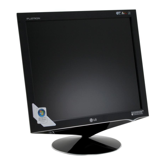
LG flatron L1760TR Service Manual
Hide thumbs
Also See for flatron L1760TR:
- Guía del usuario (23 pages) ,
- Brochure (34 pages) ,
- User manual (24 pages)
Table of Contents
Advertisement
COLOR MONITOR
SERVICE MANUAL
CHASSIS NO. : LM57D
MODEL:
(
) **Same model for Service
CAUTION
BEFORE SERVICING THE UNIT,
READ THE SAFETY PRECAUTIONS IN THIS MANUAL.
E-mail:http://www.LGEservice.com/techsup.html
L1760TR (L1760TR-BFQ.A**XQP, A**MQP)
L1960TR (L1960TR-BFQ.A**XQP, A**MQP)
Website:http://biz.LGservice.com
Advertisement
Table of Contents

Related Manuals for LG flatron L1760TR


Summary of Contents for LG flatron L1760TR
- Page 1 Website:http://biz.LGservice.com E-mail:http://www.LGEservice.com/techsup.html COLOR MONITOR SERVICE MANUAL CHASSIS NO. : LM57D MODEL: L1760TR (L1760TR-BFQ.A**XQP, A**MQP) L1960TR (L1960TR-BFQ.A**XQP, A**MQP) ) **Same model for Service CAUTION BEFORE SERVICING THE UNIT, READ THE SAFETY PRECAUTIONS IN THIS MANUAL.
-
Page 2: Table Of Contents
CONTENTS SPECIFICATIONS ........... 2 SERVICE OSD ............13 PRECAUTIONS ............3 TROUBLESHOOTING GUIDE ......14 TIMING CHART ............7 WIRING DIAGRAM ..........18 DISASSEMBLY ............8 EXPLODED VIEW...........19 BLOCK DIAGRAM.............9 REPLACEMENT PARTS LIST .......21 DISCRIPTION OF BLOCK DIAGRAM ....10 ADJUSTMENT ............12 SCHEMATIC DIAGRAM ......... -
Page 3: Precautions
PRECAUTION WARNING FOR THE SAFETY-RELATED COMPONENT. WARNING • There are some special components used in LCD BE CAREFUL ELECTRIC SHOCK ! monitor that are important for safety. These parts are • If you want to replace with the new backlight (CCFL) or marked on the schematic diagram and the inverter circuit, must disconnect the AC adapter... -
Page 4: Servicing Precautions
SERVICING PRECAUTIONS CAUTION: Before servicing receivers covered by this 9. Use with this receiver only the test fixtures specified in service manual and its supplements and addenda, read this service manual. and follow the SAFETY PRECAUTIONS on page 3 of this CAUTION: Do not connect the test fixture ground strap publication. - Page 5 General Soldering Guidelines Replacement 1. Use a grounded-tip, low-wattage soldering iron and 1. Carefully insert the replacement IC in the circuit board. appropriate tip size and shape that will maintain tip 2. Carefully bend each IC lead against the circuit foil pad and solder it.
- Page 6 Circuit Board Foil Repair At Other Connections Excessive heat applied to the copper foil of any printed Use the following technique to repair the defective copper circuit board will weaken the adhesive that bonds the foil pattern at connections other than IC Pins. This technique to the circuit board causing the foil to separate from or involves the installation of a jumper wire on the "lift-off"...
-
Page 7: Timing Chart
TIMING CHART VIDEO SYNC Total Video Sync Front Blanking Sync MODE H / V Frequency Duration Porch Time Resolution Period Active Polarity Clock ( D ) ( C ) ( B ) ( E ) Time ( A ) H(Pixels) 25.175 31.469 640 x 350... -
Page 8: Disassembly
DISASSEMBLY Disassemble Rear Cover. Remove the screws. # 4-1 Remove the screws. Disassembly the like a picture. # 4-2 Disassembly the like a picture. - 8 -... -
Page 9: Block Diagram
BLOCK DIAGRAM - 9 -... -
Page 10: Description Of Block Diagram
DESCRIPTION OF BLOCK DIAGRAM 1. Video Controller Part. This part amplifies the level of video signal for the digital conversion and converts from the analog video signal to the digital video signal using a pixel clock. The pixel clock for each mode is generated by the PLL. The range of the pixel clock is from 25MHz to 135MHz. -
Page 11: Lips Board Block Diagram
LIPS Board Block Diagram 50 ~ 60Hz 100KHz HVDC INPUT RECTIFIER OUTPUT RECTIFIER SWITCHING COMPONENTS AND FILTER TRANSFORMER AND FILTER LINE 100 ~ 240V SIGNAL PHOTO- COLLENT- CONTROL COUPLER CIRCUIT ISOLATION PRIMARY SECONDARY INVERTER CIRCUIT High Voltage Operation description_LIPS 1. EMI components. This part contains of EMI components to comply with global marketing EMI standards like FCC,VCCI CISPR, circuit included a line-filter, across line capacitor and of course the primary protection fuse. -
Page 12: Adjustment
ADJUSTMENT Windows EDID V1.0 User Manual 2. EDID Read & Write 1) Run WinEDID.exe Operating System: MS Windows 98, 2000, XP Port Setup: Windows 98 => Don’t need setup Windows 2000, XP => Need to Port Setup. This program is available to LCD Monitor only. 1. -
Page 13: Service Osd
SERVICE OSD 1) Turn off the power switch at the front side of the display. 2) Wait for about 5 seconds and press MENU, POWER switch with 1 second interval. 3) The SVC OSD menu contains additional menus that the User OSD menu as described below. a) Auto Color : W/B balance and Automatically sets the gain and offset value. -
Page 14: Troubleshooting Guide
TROUBLESHOOTING GUIDE 1. NO POWER NO POWER (POWER INDICATOR OFF) CHECK J405 CHECK ADAPTER AND VOLTAGE TEST WITH ANOTHER ONE PIN3 (12V)? CHECK CHECK U503 AND U503 PIN 5 VOLTAGE AROUND CIRCUIT (5V) ? IS U501 PIN3 (3.3V) CHECK U501 VOLTAGE ? IS U502 PIN2 (1.8V) - Page 15 2. NO RASTER (OSD IS NOT DISPLAYED) – INVERTER NO RASTER (OSD IS NOT DISPLAYED) CHECK 12V LINE, AND J403 FIND OUT A OPEN POINT PIN1, PIN2 AS OPENING EACH 12V? POWER LINE CHECK MICOM INV J403 PIN7 ON/OFF PORT. 3.3V? J305 PIN6 CHECK SCALER DIM-ADJ...
- Page 16 3. NO RASTER (OSD IS NOT DISPLAYED) – MSTAR NO RASTER (OSD IS NOT DISPLAYED) U101 PIN 71, 87 CHECK U501 3.3V? U101 1. CHECK C110, C109 SOLDERING CONDITION PIN127, 128 OSCILLATE AS 2. CHECK X101 14.31MHZ? 3. TROUBLE IN U101 U101 PIN32 IS 48KHz H-SYNC? CHECK CONNECTION...
- Page 17 4. TROUBLE IN DPM TROUBLE IN DPM CHECK PC CHECK PC IS NOT GOING R442, R443 INTO DPM OFF MODE CHECK U101 PIN 32,33 CHECK H/V SYNC LINE SYNC PULSE ? TROUBLE IN U101 Waveforms 3 R443 V-Sync R442 H-Sync - 17 -...
-
Page 18: Wiring Diagram
WIRING DIAGRAM 6631900109B-L1760TQ 6631900109A-L1960TQ 6631T12006F EAD30507301 6631V12031A - 18 -... -
Page 19: Exploded View
EXPLODED VIEW - 19 -... -
Page 20: Exploded View Parts List
EXPLODED VIEW PARTS LIST * Note: Safety mark Ref. No. Part No. Description 30919L0031E Cover Assembly, L1760 . 17" L1760TR 30919L0031F Cover Assembly, L1760 . 17" L1760 "E"-CKD 30919L0032D Cover Assembly, L1960TR LM57D 19" L1960TR CABINET 30919L0032H Cover Assembly, L1960 LM57D 19" L1960TR D-CKD EAJ32188801 LCD,Module-TFT, LM170E03-TLB3 DRIVER 17.0INCH 1280X1024 300CD COLOR 72% 5/4 800 VS 1 5MS, 160/160, 4LAMP, 2CH-LVDS EAJ32188901... -
Page 21: Replacement Parts List
REPLACEMENT PARTS LIST CAUTION: BEFORE REPLACING ANY OF THESE COMPONENTS, READ CAREFULLY THE SAFETY PRECAUTIONS IN THIS MANUAL. * NOTE SAFETY Mark AL ALTERNATIVE PARTS DATE: 2006. 10. 16. DATE: 2006. 10. 16. *S *AL LOC. NO. PART NO. DESCRIPTION / SPECIFICATION *S *AL LOC. - Page 22 DATE: 2006. 10. 16. DATE: 2006. 10. 16. *S *AL LOC. NO. PART NO. DESCRIPTION / SPECIFICATION *S *AL LOC. NO. PART NO. DESCRIPTION / SPECIFICATION ZD406 0DZ560009GB BZT52C5V6S-(F) 5.6V 5.2TO6V R415 0RJ4701D677 MCR03EZPJ472 4.7KOHM 5% 1/10 ZD407 0DZ560009GB BZT52C5V6S-(F) 5.6V 5.2TO6V R416 0RJ4701D677 MCR03EZPJ472 4.7KOHM 5% 1/10...
- Page 23 DATE: 2006. 10. 16. *S *AL LOC. NO. PART NO. DESCRIPTION / SPECIFICATION R703 0RJ1201D677 MCR03EZPJ122 1.2KOHM 5% 1/10 R704 0RJ1801D677 MCR03EZPJ182 1.8KOHM 5% 1/10 SW701 6600R00004A JTP1138A6EM 1C2P 12VDC 50MA SW702 6600R00004A JTP1138A6EM 1C2P 12VDC 50MA SW703 6600R00004A JTP1138A6EM 1C2P 12VDC 50MA SW704 6600R00004A JTP1138A6EM 1C2P 12VDC 50MA...
-
Page 24: Schematic Diagram
SCHEMATIC DIAGRAM 1. SCALER - 24 -... - Page 25 2. POWER & WAFER - 25 -...
- Page 26 3. DC-DC BLOCK - 26 -...
- Page 27 Oct. 2006 P/NO : MFL30105567 Printed in Korea...
Need help?
Do you have a question about the flatron L1760TR and is the answer not in the manual?
Questions and answers