
Subscribe to Our Youtube Channel
Related Manuals for Hoshizaki KM-100A


Summary of Contents for Hoshizaki KM-100A
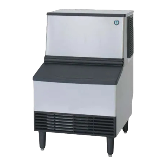
- Page 1 NO. F003-756 ISSUED: JUN. 18, 2008 REVISED: JUN. 17, 2011 HOSHIZAKI SELF-CONTAINED CRESCENT CUBER KM-100A MODEL KM-125A SERVICE MANUAL...
-
Page 2: Table Of Contents
1. SPECIFICATIONS ----------------------------------------------------------------------------------1 [a] KM-100A ------------------------------------------------------------------------------------------1 [b] KM-125A ------------------------------------------------------------------------------------------2 II. GENERAL INFORMATION -------------------------------------------------------------------------3 1. CONSTRUCTION ----------------------------------------------------------------------------------3 [a] KM-100A, KM-125A ---------------------------------------------------------------------------3 [b] ICEMAKING COMPARTMENT -------------------------------------------------------------4 2. SEQUENCE OF OPERATION ------------------------------------------------------------------5 [a] ONE MINUTE FILL CYCLE ------------------------------------------------------------------5 [b] INITIAL HARVEST CYCLE ------------------------------------------------------------------5... - Page 3 IV. SERVICE DIAGNOSIS ---------------------------------------------------------------------------- 26 1. 10-MINUTE DIAGNOSTIC PROCEDURE ------------------------------------------------- 26 2. NO ICE PRODUCTION ------------------------------------------------------------------------- 28 3. EVAPORATOR IS FROZEN UP -------------------------------------------------------------- 31 4. LOW ICE PRODUCTION ----------------------------------------------------------------------- 32 5. ABNORMAL ICE ---------------------------------------------------------------------------------- 32 6. OTHER ---------------------------------------------------------------------------------------------- 33 V. REMOVAL AND REPLACEMENT -------------------------------------------------------------- 34 1.
-
Page 4: Specifications
I. SPECIFICATIONS 1. SPECIFICATIONS [a] KM-100A AC SUPPLY VOLTAGE 1 Phase 220-240 50Hz AMPERAGE 3.40 (AT. 32°C, WT. 21°C) STARTING AMPERAGE 15 A ELECTRICAL CONSUMPTION 584W (AT. 32°C, WT. 21°C) POWER FACTOR 67 % POWER SUPPLY CAPACITY 0.96 kVA (4.2A) Approx. 101 kg (AT. 10°C, WT. 10°C) ICE PRODUCTION PER 24h Approx. 88 kg (AT. 21°C, WT. 15°C) Approx. 64 kg (AT. 32°C, WT. 21°C) (AT. 10°C, WT. 10°C) Approx. 0.54 m WATER CONSUMPTION PER 24h Approx. 0.22 m (AT. 21°C, WT. 15°C) Approx. 0.11 m (AT. 32°C, WT. 21°C) SHAPE OF ICE Crescent Cube FREEZE CYCLE TIME Approx. 26 min (AT. 21°C, WT. 15°C) ICE PRODUCTION PER CYCLE Approx. 1.7 kg / 182 pcs (AT. 21°C, WT. 15°C) MAX STORAGE CAPACITY Approx. 45 kg (Bin Cont Setting Approx. 35 kg) DIMENSIONS 610mm (W) X 712mm (D) X 840mm (H) (+152mm Leg) EXTERIOR... -
Page 5: [B] Km-125A
[b] KM-125A AC SUPPLY VOLTAGE 1 Phase 220-240 50Hz AMPERAGE 4.50 A (AT. 32°C, WT. 21°C) STARTING AMPERAGE 19 A ELECTRICAL CONSUMPTION 774W (AT. 32°C, WT. 21°C) POWER FACTOR 67 % POWER SUPPLY CAPACITY 1.43 KVA (5.9A) Approx. 128 kg (AT. 10°C, WT. 10°C) ICE PRODUCTION PER 24h Approx. 115 kg (AT. 21°C, WT. 15°C) Approx. 102 kg (AT. 32°C, WT. 21°C) Approx. 0.73 m (AT. 10°C, WT. 10°C) WATER CONSUMPTION PER 24h Approx. 0.40 m (AT. 21°C, WT. 15°C) Approx. 0.18 m (AT. 32°C, WT. 21°C) SHAPE OF ICE Crescent Cube FREEZE CYCLE TIME Approx. 24 Min (AT. 21°C, WT. 15°C) ICE PRODUCTION PER CYCLE Approx. 2.1 kg / 238 pcs (AT. 21°C, WT. 15°C) MAX STORAGE CAPACITY Approx. 55 kg (Bin Cont Setting Approx. 45 kg) DIMENSIONS 762mm (W) X 712mm (D) X 840mm (H) (+152mm Leg) EXTERIOR Stainless Steel, Plastic Door, Galvanized Steel (Rear) INSULATION Polyurethane Foam CONNECTIONS-ELECTRIC X-type Connection (With Plug) -WATER SUPPLY Inlet G1/2" (connected at rear side) -
Page 6: General Information
II. GENERAL INFORMATION 1. CONSTRUCTION [a] KM-100A, KM-125A Top Panel Side Panel (L) Front Cover Rear Panel Door Air Filter Duct Louver Leg Side Panel (R) Power Supply Cord Top Cover Hot Gas Valve Thermistor Evaporator Drain Valve Condenser Fan Motor Separator Compressor Water Tank Water Valve Expansion Float Switch Valve Overflow Pipe Drier Pump Motor Control Switch Service Switch Control Box Front View... -
Page 7: [B] Icemaking Compartment
[b] ICEMAKING COMPARTMENT Spray Tube Evaporator Water Supply Pipe Separator Cube Guide Water Tank Overflow Pipe Drain Valve Separator Water Valve Pump Motor Float Switch... -
Page 8: Sequence Of Operation
2. SEQUENCE OF OPERATION The steps in the sequence are as outlined below. When power is supplied, a 5 second delay occurs at startup. Note that the order of the LEDs from the outer edge of the board is 5, 6, 8, 4, 7. [a] ONE MINUTE FILL CYCLE LED 8 is on. WV opens and the fill period begins. After 1 minute, the board checks for a closed F/S. If F/S is closed, the harvest cycle begins. If not, WV will remain energized through additional 1 minute cycles until water enters the sump and F/S closes. This serves as a low water safety to protect the water pump. [b] INITIAL HARVEST CYCLE LEDs 5, 6, and 8 are on. WV remains open, Comp energizes, HGV opens, and harvest begins. As the evaporator warms, the thermistor located on the suction line checks for a 9°C temperature. When 9°C is reached, a 3.9 kΩ signal turns the harvest over to the adjustable harvest timer which is factory set for normal conditions. The timer has settings of 60, 90, 120, and 180 seconds (S1 dip switch 1 & 2). When the harvest timer... -
Page 9: [D] Drain Cycle
[d] DRAIN CYCLE LEDs 4, 5, 6, and 7 are on. Comp continues to run, HGV opens, and FMS de-energizes. PM stops for 2 seconds, DV energizes, then restarts to take water from the sump and force it through DV and down the drain. When the drain timer stops counting, the drain is complete. The drain timer has settings of 10 and 20 seconds (S1 dip switch 3 & 4). Drain cycle always occurs on the 2nd harvest after startup. Then, depending on the control board setting, drain cycle occurs every cycle, or every 2nd, 5th, or 10th cycle (S1 dip switch 5 & 6). [e] NORMAL HARVEST CYCLE LEDs 5, 6, and 8 are on. Comp continues to run, HGV remains open and WV opens. As the evaporator warms, the thermistor reaches 9°C. The control board then receives the thermistor's 3.9 kΩ signal and starts the harvest timer. WV is open during harvest for a maximum of 6 minutes or the length of harvest minus 0, 10, 30, or 50 seconds (adjustable by S1 dip switch 7 & 8), whichever is shorter. LED 8 goes off when WV closes. PM energizes and runs for the last 0, 10, 30, or 50 seconds of harvest depending on S1 dip switch 7 & 8 setting. LED 7 comes on when PM energizes. At the end of harvest, the control board checks the position of F/S and proceeds to the freeze cycle if it is closed... -
Page 11: Control Board
3. CONTROL BOARD * A HOSHIZAKI exclusive solid-state control is employed in KM-100A and KM-125A Crescent Cubers. * All models are pretested and factory-adjusted. CAUTION 1. Fragile, handle very carefully. 2. A control board contains integrated circuits, which are susceptible to failure due to static discharge. It is especially important to touch the metal part of the unit before handling or replacing the board. -
Page 12: [A] Control Board Layout
[a] CONTROL BOARD LAYOUT "H" Control Board Relay LEDs (6) Connector K7 (indicate which relays Transformer are energized as listed below) LED 5 (X1 Relay) Compressor (Comp) Remote Fan Motor (FMR) LED 6 (X2 Relay) Connector K3 Hot Gas Valve (HGV) Magnetic Contactor Self-Contained Fan Motor (FMS) (FMS off Connector K4 when LED on) Open LED 8 (X4 Relay) POWER OK LED Inlet Water Valve (WV) (Lights when power is (Harvest Water Valve supplied to the board. (HWV) on units with Flashes when bin control two inlet water valves) is activated.) LED 9 (X5 Relay) Connector K5 Freeze Water Valve Pins (FWV) on units with #1 Fan Motor two inlet water valves... -
Page 13: [B] Features
[b] FEATURES a) Maximum Water Supply Period - 6 minutes The inlet water valve will be open during harvest for 6 minutes or the length of harvest minus 0, 10, 30, or 50 seconds (adjustable by S1 dip switch 7 & 8), whichever is shorter. b) Harvest Backup Timer and Freeze Timer The harvest backup timer shuts down the icemaker if, for two cycles in a row, the harvest cycle takes more than 20 minutes to complete. The control board will signal this problem using 2 beeps every 3 seconds. The freeze timer shuts down the icemaker if, for two cycles in a row, the freeze cycle takes longer than the time specified to complete. The control board will signal this problem using 3 beeps every 3 seconds. The time is factory set using S1 dip switch 9 &... - Page 14 seconds and the icemaker automatically stops. The control board will signal this problem using 7 beeps every 3 seconds. The icemaker also automatically stops in cases of insufficient voltage (184Vac ± 5% or less). The control board will signal this problem using 6 beeps every 3 seconds. When the proper supply voltage is resumed, the icemaker automatically starts running again. f) LED Lights and Audible Alarm Safeties The control board includes LED indicator lights, audible alarm safeties, and an output test feature. The "POWER OK" LED indicates control voltage and will remain on unless a control voltage problem occurs. The “POWER OK” LED flashes continuously when the bin is full and DV energizes for a maximum of 5 minutes to drain the water tank. At startup, a 5 second delay occurs to stabilize the circuit. LEDs 4 through 8 energize and sequence from initial startup as listed in the table below. Note that the order of the LEDs from the outer edge of the board is 5, 6, 8, 4, 7. For more information, see "2. SEQUENCE OF OPERATION".
-
Page 15: [C] Controls And Adjustments
(294Vac ± 5% or more) Legend: Comp–compressor; DV–drain valve; FMS–self-contained fan motor; HGV–hot gas valve; PM–pump motor; TXV–thermostatic expansion valve; WRV–water regulating valve; WV–inlet water valve [c] CONTROLS AND ADJUSTMENTS a) Default Dip Switch Settings The dip switch is factory-adjusted to the following positions: S1 Dip Switch No. KM-100A KM-125A Program Ver. Control Board S2 Dip Switch No. (Auxiliary Code) KM-100A ON OFF OFF OFF OFF ON 2.5 or earlier P00013-02... - Page 16 thermistor reads a certain temperature at the evaporator outlet. Dip Switch Setting Time No. 1 No. 2 (seconds) c) Drain Timer (S1 dip switch 3 & 4) Once every ten freeze cycles, the drain valve opens to drain the water tank for the time determined by the drain timer. These switches also determine the time to delay completion of a defrost cycle, i.e. the minimum defrost time.
- Page 17 e) Water Saver Timer (S1 dip switch 7 & 8) The water saver timer allows the water valve to close and the pump motor to circulate water in the tank during the final part of harvest. The water valve is open during harvest for a maximum of 6 minutes or the length of harvest minus 0, 10, 30, or 50 seconds (determined by the water saver timer setting), whichever is shorter. When the water valve closes, the pump motor energizes and runs for the time determined by the water saver timer setting.
- Page 18 Refill Counter (S2 dip switch 2, 3, & 4) [Program Ver. 2.5 or earlier] Do not adjust. These must be left in the factory default position or the unit will not operate properly. The KM-100A and KM-125A do not refill. i) Anti-Slush Control (S2 dip switch 5 & 6) [Program Ver. 2.5 or earlier] Do not adjust. These must be left in the factory default position or the unit will not...
- Page 19 Refill Counter (S2 dip switch 3) [Program Ver. 3.1, Ver. 3.2] Do not adjust. This must be left in the factory default position or the unit will not operate properly. The KM-100A and KM-125A do not refill. l) Harvest Completion Detection Control (S2 dip switch 4) [Program Ver. 3.1, Ver. 3.2] Do not adjust. This must be left in the factory default position or the unit will not operate properly. It is deactivated on the KM-100A and KM-125A. When activated, this control determines whether ice remains on the evaporator at the end of a harvest cycle and at the beginning of a freeze cycle. If ice drops and activates...
-
Page 20: [D] Control Board Check Procedure
n) Anti-Slush Control (S2 dip switch 6) [Program Ver. 3.1] Do not adjust. This must be left in the factory default position or the unit will not operate properly. When activated (Ver. 2.0), the thermistor located on the suction line checks for a 50°F (10°C) temperature as the evaporator cools. When 50°F (10°C) is reached, a 3.9 kΩ signal causes the control board to de-energize the pump motor for 10 seconds and energize it for 50 seconds repeatedly. When 34°F (1°C) is reached, a 5.9 kΩ signal causes the control board to de-energize the pump motor for 10 seconds, energize it for 50 seconds, de-energize it again for 10 seconds, then energize it continuously. -
Page 21: [E] Control Board Replacement
2) Move the control switch to the “ICE” position and check for proper control voltage. If the “POWER OK” LED is on, the control voltage is good. If the “POWER OK” LED is off, check the control transformer circuit. If no voltage is present, check the power supply circuit. 3) To perform a relay sequence test, turn on the power switch while pressing the "OUTPUT TEST" button. The correct lighting sequence should be 5, 6, 7, 8, 4. Some components (e.g., the compressor) will cycle during test. Each LED comes on for 5 seconds. LED 5 is on while LED 6 is on. Following the output test sequence, the icemaker will resume normal operation beginning with the 1 minute fill cycle. -
Page 22: Bin Control
5. BIN CONTROL This machine uses a lever-actuated proximity switch (mechanical bin control) to control the ice level in the storage bin. No adjustment is required. [a] EXPLANATION OF OPERATION The bin control is connected to the K1 connector (pins 4 & 5) on the control board. When the bin control is calling for ice (proximity switch closed; "POWER OK" LED on), the control board continues icemaking operations. When the bin control is activated in the bin full position (proximity switch open; "POWER OK" LED flashing), the control board drains and shuts down the unit. However, to prevent incomplete batches of ice from forming on the evaporator, the control board will only shut down the machine during the freeze cycle before the five minute timer expires. The five minute timer starts... -
Page 23: Switches
6. SWITCHES Two different control switches are used for operation of KM-100A and KM-125A. They are located on the right side of the control box which becomes accessible when the front louver is removed. The upper is the control switch, and the lower is the service switch. [a] CONTROL SWITCH This switch is used to place the machine into one of three modes: “OFF” (center position), “ICE” (upper position), and “SERVICE” (lower position). [b] SERVICE SWITCH When the control switch is placed in the “SERVICE” position, power is supplied to the service switch. The service switch can be used to perform two functions: draining the tank (“DRAIN” = lower position) and washing the icemaking compartment (“WASH” or... -
Page 24: Technical Information
III. TECHNICAL INFORMATION 1. WATER CIRCUIT AND REFRIGERANT CIRCUIT... -
Page 25: Wiring Diagram
2. WIRING DIAGRAM [a] PRODUCTION 2008 (Auxiliary Code: T-1, U-1) -
Page 26: [B] Production 2009 (Auxiliary Code: U-1) Or Later
[b] PRODUCTION 2009 (Auxiliary Code: U-1) OR LATER... -
Page 29: Service Diagnosis
IV. SERVICE DIAGNOSIS 1. 10-MINUTE DIAGNOSTIC PROCEDURE The 10 minute check out procedure is basically a sequence check which can be used at unit start-up or for system diagnosis. Using this check out procedure will allow you to diagnose electrical system and component failures in approximately 10 minutes under normal operating conditions of 21°C or warmer air and 10°C or warmer water temperatures. Before conducting a 10 minute checkout, check for correct installation, proper voltage per unit nameplate and adequate water supply. As you go through the procedure, check to assure the components energize and de-energize correctly. If not,... - Page 30 starts after the thermistor temperature reaches 2°C. After this period, the freeze cycle operation is transferred to the float switch for freeze termination. During the first 5 minutes of freeze, confirm that the evaporator temperature drops. After the minimum freeze period, disconnect the float switch at the 2-pin connector attached to the red wires. The unit should immediately switch to the drain cycle. Diagnosis: If the evaporator is not cold, check to see if the hot gas valve is still open or if the expansion valve is not opening properly, if the water valve is continuing to fill the...
-
Page 31: No Ice Production
2. NO ICE PRODUCTION PROBLEM POSSIBLE CAUSE REMEDY [1] The icemaker a) Power Supply 1. OFF position. 1. Move to ON position. will not start. 2. Loose connections. 2. Tighten. 3. Bad contacts. 3. Check for continuity and replace. 4. Voltage too high. 4. - Page 32 PROBLEM POSSIBLE CAUSE REMEDY [2] Water a) Float Switch 1. Connector 1. Reconnect. continues to disconnected. be supplied, 2. Leads opened or 2. Check and replace. and the defective switch. icemaker will 3. Float does not move 3. Clean or replace. not start.
- Page 33 PROBLEM POSSIBLE CAUSE REMEDY [5] No water a) Water Supply Line 1. Water pressure too low 1. Check and get comes from and water level in Water recommended pressure. Spray Tubes. Tank too low. Water Pump b) Inlet Water Valve 1.
-
Page 34: Evaporator Is Frozen Up
3. EVAPORATOR IS FROZEN UP PROBLEM POSSIBLE CAUSE REMEDY [1] Freeze cycle a) Float Switch 1. Leads shorted or 1. Check and replace. time is too defective switch. long. 2. Float does not move 2. Clean or replace. freely. b) Inlet Water Valve 1. -
Page 35: Low Ice Production
4. LOW ICE PRODUCTION PROBLEM POSSIBLE CAUSE REMEDY [1] Freeze cycle a) See chart 2 - [3] and check dirty Air Filter or Condenser, ambient or water time is long. temperature, water pressure, and refrigerant charge. b) See chart 3 - [1] and check Float Switch, Inlet Water Valve, and Control Board. -
Page 36: Other
6. OTHER PROBLEM POSSIBLE CAUSE REMEDY [1] Icemaker will a) Bin Control Switch 1. Completely 1. Place in position. not stop when disconnected and bin is filled with dropped inside bin. ice. 2. Detector broken. 2. Replace. 3. Detector out of position. 3. -
Page 37: Removal And Replacement
V. REMOVAL AND REPLACEMENT 1. SERVICE FOR REFRIGERANT LINES [a] SERVICE INFORMATION 1) Allowable Compressor Opening Time and Prevention of Lubricant Mixture [R404A] The compressor must not be opened more than 15 minutes in replacement or service. Do not mix lubricants of different compressors even if both are charged with the same refrigerant, except when they use the same lubricant. 2) Treatment for Refrigerant Leak [R404A] If a refrigerant leak occurs in the low side of an ice maker, air may be drawn in. Even if the low side pressure is higher than the atmospheric pressure in normal operation, a continuous refrigerant leak will eventually lower the low side pressure below the atmospheric pressure and will cause air suction. Air contains a large amount of moisture, and ester oil easily absorbs a lot of moisture. If an ice maker charged with R404A has... -
Page 38: [B] Refrigerant Recovery
type copper tubes are used in the shipped units.) 7) Evacuation, Vacuum Pump and Refrigerant Charge [R404A] Never allow the oil in the vacuum pump to flow backward. The vacuum level and vacuum pump may be the same as those for the current refrigerants. However, the rubber hose and gauge manifold to be used for evacuation and refrigerant charge should be exclusively for R404A. -
Page 39: Brazing
8) Repeat steps 4) through 7), if necessary, until the required amount of refrigerant has entered the system. 9) Close the Refrigerant Access Valve, and disconnect the Hoses, Service Manifold, etc. 10) Cap the Access Valve to prevent possible leak. Depressed Access Valve OPEN Fig. 3 2. BRAZING DANGER 1. Refrigerant R404A itself is not explosive or poisonous. However, when exposed to high temperatures (open flames), R404A can be decomposed to form hydrofluoric acid and carbonyl fluoride both of which are hazardous. -
Page 40: Compressor
3. COMPRESSOR WARNING The Compressor Terminal Cover must be refitted in its correct position. Otherwise, operation under high temperature and high humidity conditions may cause electric shock, fire, or corrosion to shorten the service life. IMPORTANT Always install a new Drier every time the sealed refrigeration system is opened. Do not replace the Drier until after all other repair or replacement has been made. 1) Unplug the icemaker or disconnect the power source. 2) Remove the Top Panel and Rear Panel. 3) Recover the refrigerant and store it in a proper container, if required by an applicable law (see “1. [b] REFRIGERANT RECOVERY”). 4) Remove the Terminal Cover on the Compressor, and disconnect Solderless Terminals. -
Page 41: Drier
RECHARGE”). 16) Connect the Solderless Terminals and replace the Terminal Cover in its correct position. 17) Refit the panels in their correct positions. 18) Plug in the icemaker or connect the power source. Note: Hoshizaki recommends that Compressor starting electrics are always replaced at the same time as the Compressor. 4. DRIER IMPORTANT Always install a new Drier every time the sealed refrigeration system is opened. Do not replace the Drier until after all other repair or replacement has been made. 1) Unplug the icemaker or disconnect the power source. 2) Remove the Top Panel and Rear Panel. 3) Recover the refrigerant and store it in a proper container, if required by an applicable law (see “1. [b] REFRIGERANT RECOVERY”). -
Page 42: Hot Gas Valve
5. HOT GAS VALVE CAUTION To ensure optimum performance, use a copper tube of the same diameter and length for replacement of the hot gas circuit. IMPORTANT Always install a new Drier every time the sealed refrigeration system is opened. Do not replace the Drier until after all other repair or replacement has been made. 1) Unplug the icemaker or disconnect the power source. 2) Remove the Top Panel, Rear Panel and Side Panel (R). 3) Recover the refrigerant and store it in a proper container, if required by an applicable law (see “1. [b] REFRIGERANT RECOVERY”). 4) Disconnect the Hot Gas Valve leads. 5) Remove the screw and the Solenoid Coil. 6) Remove the valve and Drier using brazing equipment. 7) Braze the new Hot Gas Valve with nitrogen gas flowing at a pressure of 0.2 - 0.3 bar. Hot Gas Valve Fig. 4... -
Page 43: Expansion Valve
WARNING Always protect the valve body by using a damp cloth to prevent the valve from overheating. Do not braze with the valve body exceeding 135°C. 8) Install the new Drier (see “4. DRIER”). 9) Check for leaks using nitrogen gas (10 bar) and soap bubbles. 10) Evacuate the system and charge it with refrigerant (see “1. [c] EVACUATION AND RECHARGE”). 11) Attach the Solenoid Coil to the valve body, and secure it with the screw. 12) Connect the lead wires. 13) Refit the panels in their correct positions. 14) Plug in the icemaker or connect the power source. 6. EXPANSION VALVE IMPORTANT The water in the refrigeration circuit may exceed the capacity of the Drier and freeze in the Expansion Valve. Always install a new Drier every time the sealed refrigeration system is opened. Do not replace the Drier until after all other repair or replacement has been made. - Page 44 7) Braze in the new Expansion Valve. Protect the body of the valve from excessive heat, and use nitrogen at a pressure of 0.2 - 0.3 bar when brazing. 8) Install the new Drier (see “4. DRIER”). 9) Check for leaks using nitrogen gas (10 bar) and soap bubbles. 10) Evacuate the system and charge it with refrigerant (see “1. [c] EVACUATION AND RECHARGE”). 11) Attach the Bulb to the suction line in position. Be sure to secure it using a wire or clamp and replace the insulation. 12) Refit the panels in their correct positions. 13) Plug in the icemaker or connect the power source. WARNING Always protect the valve body by using a damp cloth to prevent the valve from overheating. Do not braze with the valve body exceeding 115°C.
-
Page 45: Fan Motor
7. FAN MOTOR 1) Unplug the icemaker or disconnect the power source. 2) Remove the Top Panel, Rear Panel and Side Panel (L). 3) Disconnect the Connector of the Fan Motor lead. 4) Remove the four screws securing the Fan Motor Bracket and pull out the Fan Motor in the arrow direction. To prevent deformation, do not hit the Fan on the Condenser or other parts. 5) Install the new Fan Motor in the reverse order of the removal procedure. 6) Refit the panels in their correct positions. 7) Plug in the icemaker or connect the power source. Screw Fan Motor Fan Motor Bracket Fig. 6... -
Page 46: Pump Motor
8. PUMP MOTOR 1) Unplug the icemaker or disconnect the power source. 2) Remove the Top Panel, Rear Panel and Side Panel (R). 3) Disconnect the Connector of the Pump Motor lead. 4) Remove the Water Tank (see “15. WATER TANK”). 5) Remove the Hose Band connecting the Pump Motor discharge outlet and pull off the Rubber Hose. Rubber Hose Hose Band Fig. 7 Pull off 6) Remove the screws securing the Pump Motor, and lift it off. Lift off Screw Fig. 8 7) Install the new motor in the reverse order of the removal procedure. 8) Refit the Water Tank in its correct position. 9) Plug in the icemaker or connect the power source, and check for leaks. 10) Refit the panels in their correct positions. -
Page 47: Water Valve
9. WATER VALVE 1) Unplug the icemaker or disconnect the power source. 2) Close the water supply tap. 3) Remove the Top Panel, Rear Panel and Side Panel (R). 4) Disconnect the Tab Terminals. 5) Pinch and lower the Hose Clamp. 6) Disconnect the Rubber Hose from the Water Valve. Put a towel under the Water Valve to receive water coming out. 7) Turn the Inlet Nut in the arrow direction to remove it from the Water Valve. Do not lose the Gasket inside. 8) Remove the two mounting screws. 9) Install the new valve in the reverse order of the removal procedure. 10) Tighten the Inlet Nut to a torque of 7.85 N•m (±5%) to prevent water leaks. 11) Open the water supply tap. 12) Plug in the icemaker or connect the power source. 13) Check for leaks. 14) Refit the panels in their correct positions. Rubber Hose Hose Clamp Mounting Screw Tab Terminal Inlet Nut Fig. 9... -
Page 48: Drain Valve
10. DRAIN VALVE 1) Unplug the icemaker or disconnect the power source. 2) Close the water supply tap. 3) Remove the Top Panel, Rear Panel and Side Panel (R). 4) Disconnect the Tab Terminals. 5) Remove the Hose Clamps at the inlet and outlet sides. 6) Remove the Rubber Hoses at the inlet and outlet sides. 7) Remove the two mounting screws. 8) Install the new valve in the reverse order of the removal procedure. 9) Open the water supply tap. 10) Plug in the icemaker or connect the power source. 11) Check for leaks. 12) Refit the panels in their correct positions. Mounting Screw Drain Valve Fig. 10... -
Page 49: Float Switch
11. FLOAT SWITCH 1) Unplug the icemaker or disconnect the power source. 2) Remove the Top Panel, Rear Panel and Side Panel (R). 3) Disconnect the Connector of the Float Switch lead. 4) Remove the two mounting screws. 5) Install the new Float Switch in the reverse order of the removal procedure. 6) Refit the panels in their correct positions. 7) Plug in the icemaker or connect the power source. Lift off Float Switch Fig. 11... -
Page 50: Bin Control Switch
12. BIN CONTROL SWITCH 1) Remove the Water Tank (see “15. WATER TANK”). The Bin Control Switch is located as shown below when viewed from the front. Bin Control Switch Fig. 12 2) Remove the Top Panel and the Rear Panel. 3) Disconnect the Connector of the Bin Control Switch lead (black) covered with a silicone hose and remove the lead wire from the Grommet. 4) Loosen the Thumbscrew on the right side. 5) Remove the Thumbscrew on the left side. Shift the Bin Control Switch to the left to remove. 6) Refit the removed parts in the reverse order of the removal procedure. 7) Plug in the icemaker or connect the power source. Shift to the left and remove Remove Loosen Fig. 13... -
Page 51: Thermistor
13. THERMISTOR 1) Unplug the icemaker or disconnect the power source. 2) Remove the Top Panel and unscrew the Rear Panel. 3) Disconnect the Connector of the Thermistor lead (orange). 4) Remove the Ties, Insulation, Thermistor Holder, and Thermistor in this order. 5) Remove the old sealant from the Thermistor Holder and Suction Pipe. 6) Wipe off any moisture or condensation from the Suction Pipe surfaces. 7) Press a tube of the sealant KE4560RTV, manufactured by Shin-Etsu Silicones, to the recess of the Thermistor Holder. Slowly squeeze the sealant out of the tube and spread it smoothly in the recess. Do not use any sealant other than the above. 8) Attach the new Thermistor in position on the Suction Pipe and press down the Thermistor Holder over the Thermistor. Be careful not to damage the Thermistor lead. Cover the parts with the Insulation and secure them with the Ties. Keep the Thermistor inside the Thermistor Holder. After the Thermistor Holder is fitted, do not pull the Thermistor lead to move the Thermistor. -
Page 52: Control Box
14. CONTROL BOX 1) Unplug the icemaker or disconnect the power source. 2) Remove the Louver. 3) Remove the two mounting screws, and pull the Control Box toward you. 4) Refit the removed parts in the reverse order of the removal procedure. Note: After replacing the components inside the Control Box, connect and tie the wires properly in their correct position. Especially make sure that the Harness does not press the Push Buttons on the Control Board. Screw Pull toward you Control Box Control Board Power Relay Power Switch Transformer Fuse Fuse Holder Fig. 15... -
Page 53: [A] Power Switch
[a] POWER SWITCH 1) Disconnect the Tab Terminals and remove the Nut securing the Power Switch. 2) Install the new Switch in the reverse order of the removal procedure. 3) To prevent miswiring, check the terminal numbers and lead wire colors with the Wiring Label. [b] FUSE 1) Use a phillips head screwdriver to remove the Fuse Holder Cap and take out the Fuse. 2) Install the new Fuse in the reverse order of the removal procedure. [c] FUSE HOLDER 1) Disconnect the Tab Terminal and remove the Nut securing the Fuse Holder. -
Page 54: [F] Control Board Transformer
2) Install the new Relay in the reverse order of the removal procedure. 3) To prevent miswiring, check the terminal numbers and lead wire colors with the Wiring Label. [f] CONTROL BOARD TRANSFORMER 1) Disconnect the Connectors and Closed End Connectors connecting the Control Board. (The Tie securing the harness may be removed. But be careful not to break the lead wires.) 2) Remove the mounting screw and lift off the Transformer from the fit at the bottom. 3) Install the new Transformer in the reverse order of the removal procedure. 15. WATER TANK 1) Drain out the Water Tank by leaving the Control Switch in the “SERVICE” position and the Service Switch in the “DRAIN” position for several tens of seconds. -
Page 55: Cube Guide
16. CUBE GUIDE 1) Remove the Water Tank (see “15. WATER TANK”). 2) Lift off the Cube Guide out of the Water Tank. 3) To refit the Cube Guide, fit the Notches on both sides to the Stoppers in the Water Tank. 4) The unit is provided with three or four Cube Guides (quantity varies depending on model). Be sure to locate the Vertical Flanges on the outside edges. Vertical Flange Notch Cube Guide Stopper Fig. 17 17. SEPARATOR IMPORTANT 1. The Front Separator and Rear Separator are attached to the Evaporator Bracket with different lengths of Pins. The Front Separator Pins (12.7 mm) are longer than the Rear Separator Pins (9.8 mm). Do not misplace the Front and Rear Separators. - Page 56 3) Remove the Top Cover and Front Cover. See Fig. 18. 4) Disconnect the Silicone Hose from the Spray Tube, and remove the Spray Tube from the Evaporator Bracket. 5) Remove the Front Separator by pushing the Pins inserted into both sides of the Evaporator Bracket toward the center. See Fig. 18. Note: Be careful not to break the Pins. 6) The Rear Separator is hooked on the groove in the Evaporator Bracket. Remove the Rear Separator by lifting it up and down. See Fig. 18. 7) Refit the Separators in the reverse order of the removal procedure. Check that the Separators are fit correctly and can swing like a pendulum. 8) Plug in the icemaker or connect the power source. Top Cover Front Cover Spray Tube Silicone Hose Rear Separator Fig.
-
Page 57: Spray Tube, Water Supply Pipe, Spray Guide
18. SPRAY TUBE, WATER SUPPLY PIPE, SPRAY GUIDE 1) Unplug the icemaker or disconnect the power source. 2) Remove the Top Panel. 3) Remove the Top Cover. 4) Remove the Silicone Hose and Spray Tube. See Fig. 19. 5) Remove the Water Spray Pipe and Spray Guide from the Evaporator Plate. See Fig. 6) Refit the removed parts in the reverse order of the removal procedure. Check for water leaks. IMPORTANT Fit the Spray Guide securely and tightly on the Evaporator fin. Otherwise, cloudy or irregular ice cubes or performance reduction may be caused. 7) Plug in the icemaker or connect the power source. Silicone Hose Spray Tube Spray Guide Water Spray Pipe Fig. 19... -
Page 58: Door
19. DOOR 1) Open the Door. 2) Unscrew and remove the Hinges on both sides, and remove the Door. 3) Refit the removed parts in the reverse order of the removal procedure. Check that the Door opens and closes smoothly. Door Hinge Fig. 20... -
Page 59: Cleaning And Maintenance Instructions
IMPORTANT Ensure all components, fasteners and screws are securely in place after any maintenance or cleaning is done to the equipment. 1. CLEANING WARNING 1. Hoshizaki recommends cleaning this unit at least once a year. More frequent cleaning, however, may be required in some existing water conditions. 2. To prevent injury to individuals and damage to the icemaker, do not use ammonia type cleaners. -
Page 60: [B] Sanitizing Procedure
6) Pour the cleaning solution into the Water Tank. Move the Control Switch to the “SERVICE” position and the Service Switch to the “WASH” position. Close the Door. 7) After 30 minutes, move the Control Switch to the “OFF” position. 8) Same as step 4. 9) Move the Control Switch to the “ICE” position to fill the Water Tank with water. 10) After 3 minutes, move the Control Switch to the “SERVICE” position and the Service Switch to the “WASH” position. 11) After 5 minutes, move the Control Switch to the “OFF” position. 12) Same as step 4. 13) Repeat steps 9 through 12 three more times to rinse thoroughly. 14) Disconnect the Overflow Pipe. Next, remove the Water Tank by removing the two Thumbscrews and pulling the tank towards you slightly and pushing it down. Be careful to avoid breakage when handling the parts. See Fig. 16. -
Page 61: Maintenance
they were removed. 5) Same as step 1. 6) Pour the sanitizing solution into the Water Tank, and allow the sanitizer to sit for 10 minutes. 7) Move the Control Switch to the “SERVICE” position and the Service Switch to the “WASH” position. 8) After 15 minutes, move the Control Switch to the “OFF” position. 9) Move the Control Switch to the “SERVICE” position and the Service Switch to the “DRAIN” position. 10) After 2 minutes, move the Control Switch to the “OFF” position. 11) Repeat steps 5 through 10 one time. Repeat steps 9 through 12 in the Cleaning Procedure three times to rinse thoroughly. -
Page 62: [C] Air Filter
[c] AIR FILTER The plastic mesh Air Filter removes dirt or dust from the air, and keeps the Condenser from getting clogged. As the filter gets clogged, the icemaker’s performance will be reduced. Check the filter at least twice a month. When it is clogged, use warm water and a neutral cleaner to wash the filter. [d] CONDENSER Check the Condenser once a year, and clean if required by using a brush or vacuum cleaner. More frequent cleaning may be required depending on the location of the icemaker. - Page 63 “DRAIN” position. 2) After 2 minutes, move the Control Switch to the “OFF” position. 3) Open the Door. Remove all ice from the Storage Bin and clean the Storage Bin. 4) Close the Door. 5) Replace the Louver in its correct position. 6) Turn off the power supply at the breaker box. Inlet Hose Washer Stop Valve Fig. 21...
Need help?
Do you have a question about the KM-100A and is the answer not in the manual?
Questions and answers