Sign In
Upload
Manuals
Brands
York Manuals
Chiller
YCAV0227
York YCAV0227 Manuals
Manuals and User Guides for York YCAV0227. We have
1
York YCAV0227 manual available for free PDF download: Installation Operation & Maintenance
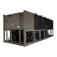
York YCAV0227 Installation Operation & Maintenance (310 pages)
Air-cooled screw liquid chillers
Brand:
York
| Category:
Chiller
| Size: 10 MB
Table of Contents
Table of Contents
5
Section 1 - General Chiller Information & Safety
9
Introduction
9
Warranty
9
Safety
9
Standards for Safety
9
Responsibility for Safety
10
About this Manual
10
Misuse of Equipment
10
Suitability for Application
10
Structural Support
10
Mechanical Strength
10
General Access
10
Pressure Systems
11
Electrical
11
Rotating Parts
11
Sharp Edges
11
Refrigerant & Oils
11
High Temperature & Pressure Cleaning
11
Emergency Shutdown
11
Section 2 - Product Description
12
Introduction
12
General System Description
12
Compressor
13
Evaporator
14
Condensor
15
Flash Tank Feed / Drain Valve
15
Oil Separator/Oil System
15
Relief Valves
15
Oil Cooling
16
Capacity Controls
16
Power and Control Panel
16
Microprocessor & VSD Controls
16
Display
17
Keypad
17
Unit Switch
17
Variable Speed Drive (VSD)
18
Fig 1 - PWM Current Waveform
18
Fig 2 - PWM Voltage Waveform
18
Accessories & Options
19
Single Point Circuit Breaker
19
Building Automation System (BAS) Interface
19
Condensor Coil Protection
19
DX Cooler Options
20
Service Valve Option
20
Unit Enclosures
20
Fans
20
Sound Reduction Options
20
Vibration Isolation
20
Unit Nomenclature
21
Product Identification Number
22
Section 3 - Rigging, Handling & Storage
26
Delivery and Storage
26
Inspection
26
Lifting Weights
26
Moving the Chiller
27
Unit Rigging
28
Section 4 - Installation
29
Location Requirements
29
Outdoor Installation
29
Indoor Installation
29
Location Clearances
30
Vibration Isolators
30
Installation
30
Shipping Braces
30
Chilled Liquid Piping
30
General Requirements
30
Positions
30
Water Treatment
32
Connection Types & Sizes
32
Cooler Connections
32
Option Flanges
32
Fig 3 - Pipework Arrangement
32
Fig 4 - Victaulic Groove
32
Fig 5 - Flange Attachment
32
Refrigerant Relief Valve Piping
33
Ductwork Connection
33
General Requirements
33
Electrical Connection
33
Power Wiring
34
Vac Control Supply Transformer
34
Control Panel Wiring
34
Volts Free Contacts
35
Chilled Liquid Pump Starter
35
Run Contact
35
Alarm Contact
35
System Inputs
35
Flow Switch
35
Remote Run/Stop
35
Optional Remote Setpoint Offset Temp
35
Optional Remote Setpoint Offset Sound Limit
35
Section 5 - Commissioning
36
Preparation
36
Preparation - Power off
36
Inspection
36
Refrigerant Charge
36
Service and Oil Line Valves
36
Compressor Oil
36
Fans
36
Isolation / Protection
36
Control Panel
36
Power Connections
37
Grounding
37
Water System
37
Flow Switch
37
Temperature Sensor(S)
37
Programmed Options
37
Programmed Settings
37
Date & Time
37
Start / Stop
37
Setpoint & Remote Offset
37
Interlocks
38
Unit Switch
38
Start-Up
38
Oil Pressure
38
Refrigerant Flow
38
Loading
38
Suction Superheat
38
Subcooling
38
Condensor & Fan Rotation
39
General Operation
39
Section 6 - Technical Data
40
Water Pressure Drop Charts
40
Glycol Correction Factors
41
Water Temp. and Flows
42
Physical Data
44
Electrical Data
49
Fig 6 - Single Point Power Supply Connection W/ Field Supplied Circuit Protection
49
Fig 7 - Single Point Power Supply Connection W/ Optional Factory Circuit Breaker
49
Electrical Notes
54
Elementary Wiring Diagram
56
Connection Diagram
60
Location Label
64
Dimensions
66
Technical Data (Clearances)
122
Weight Dist. & Isolator Mounting
124
Fig 8 - Sample Printout Supplied in the Isolator Package & Chiller Panel Literature Packet
124
Isolator Mounting Positions
125
Seismic Isolator Installation
128
Neoprene Isolator Position
130
Refrigerant Flow Diagram
133
Fig 9 - Refrigerant Flow Diagram
133
Process & Instrumentation Diagram
134
Fig 10 - Processes and Instrumentation
134
Component Locations
135
Fig 11 - Component Locations
135
Fig 12 - Control and VSD Cabinet Locations
136
Fig 13 - Chiller Control Board, Relay Boards, Microgateway, and Optional Circuit Breaker
137
Fig 14 - Chiller Control Board, Relay Boards, and Microgateway
138
Fig 15 - VSD Logic Board
139
Fig 16 - VSD Logic Board
140
Fig 17 - Power Components
141
Fig 18 - Fan Contactors & 3T Transformers
142
Fig 19 - VSD Components
143
Fig 20 - VSD Components
144
Fig 21 - VSD Components
145
Fig 22 - Inverter Power Components
146
Fig 23 - Inverter Power Components
147
Fig 24 - Inverter Power Components
148
Fig 24A - Inverter Power Components
148
Fig 25 - Glycol Pump & Fill Tube Locations
149
Fig 26 - Glycol Piping & Fill Tube Locations
150
Fig 27 - Compressor Components
151
Equipment Start-Up Check Sheet
152
Unit Checks (no Power)
152
Panel Checks
154
(Power ON-Both System Switches OFF)
154
Programmed Values
155
Chilled Liquid Setpoint
155
Date/Time, Daily Schedule, & Clock Jumper
155
Initial Start-Up
156
Check Subcooling & Superheat
156
Leak Checking
157
Chiller Electronic Components
158
Keypad
158
Display
159
Chiller Control Board
160
Relay Output Boards
161
VSD (Variable Speed Drive)
161
AC to DC Rectifier
161
SCR Trigger Board
162
DC Link Filter
162
1L Line Inductor
163
AC to DC Inverter
163
Laminated Bus Structure
163
VSD Logic Board
164
Control Panel to VSD Communications
164
IBGT Gate Driver Boards
165
Current Transformers
165
DV/DT Output Suppression Network
166
Flash Tank Feed/Drain Valve Controller
166
DC Bus Voltage Isolation Board
167
Chiller Circuit Breaker
167
Autotransformer
167
Chiller Configuration Jumpers
168
Number of Compressors Configuration Jumpers
168
Vsd Logic to Chiller Microprocessor Board Rs-485 Communication Configuration Jumpers
168
Max Vsd Frequency
169
Section 7 - Operation
170
Operating Controls
170
Basic Operating Sequence
172
Fig 28 - Chiller Control (Cooling) Range
172
Number of Compressors to Start
173
General
173
Standard IPLV
173
Optional Optimized IPLV
173
Fig 29 - Number of Compressors to Start
173
Minimum Vsd Compressor Start/Run Frequency
174
Minimum VSD Start Frequency
174
Minimum VSD Run Frequency
174
Fig 30 - Minimum VSD Start Frequency
174
Fig 31 - Minimum VSD Run
174
Acceleration/Deceleration Rate
175
Compressors
175
VSD Acceleration/ Deceleration Rates
175
Standard Iplv Capacity Control
176
Fuzzy Logic Control
177
Hot Water Starts
178
Lag Compressor Operation in Load Limiting
178
Optional Iplv Capacity Control
179
Fuzzy Logic
180
Hot Water Starts
181
Load Limiting Control
182
Flash Tank Drain/Feed Valve Controller
185
Valve Controller & Control Algorithm
185
Fig 32 - LED Locations
186
Fig 33 - Power, Comms Led's
187
Fig 34 - Power, Comms & System Open/Close Led's
187
Economizer Control
188
Condenser Fan Control
189
Fig 35 - Standard IPLV Fan Control
190
Fig 36 - High IPLV Fan Control
190
Vsd Temperature Control/Fan Control Operation
191
Remote Temperature Reset Control 1 9
192
Local Current Limit Control
193
Pulldown Current Limit Setpoint
193
Remote Current Limit Reset
194
Sound Limit Controls
196
Section 8 - Micropanel
198
Vsd Operation & Controls
198
VSD Cooling and Cooling Loop
200
Vsd Safeties
204
IBGT Gate Driver (Hardware) Fault
207
Power Supply (Hardware) Fault
209
Unit Warnings
212
Unit Safeties
216
System Safeties
218
Status Key
224
Unit Data Key
228
System Data Key
230
Vsd Data Key
234
Operating Hours & Start Keys
236
History Key
237
Unit Data
239
VSD Data
239
System Data
240
Compressor Operating Hours & Starts
242
Chilled Liquid & Cooling Setpoints
242
Options
242
Program Values
243
Setpoints Key
245
Program Key
247
Options Key
250
Date/Time & Schedule Key
254
Date/Time Key
254
Schedule Key
255
Unit Operating Schedule
256
Sound Limit Schedule
257
Manual Override Key
258
Print Key
259
Operating Data Printout
260
History Data Printout
261
Service Key
262
System Switches Key
268
Serial Number Programming
269
Enabling Optimized High Iplv Mode
271
Unit Setup Mode
272
Default Programmable Values
274
Serial Port Connections
275
Analog Input Connections
276
Digital Input Connections
278
Analog Output Connections
280
Digital Output Connections
282
Isn Communications & Transmitted Data
284
R-134A Conversion Tables
290
Maintenance
291
General Requirements
291
Maintenance Requirements
292
Troubleshooting Guide
294
Evacuating a System
296
Warranty Policy
297
New Equipment
297
Reconditioned or Replacement Materials
297
All Warranties Are VIOD if
297
Sensor Input Voltage Table
298
Outside Air Temp Sensor Input Voltage Table
299
Pressure Transducer Output Voltage Table
300
Motor Temperature Sensor Resistance Table
301
Compressor Motor Overload Settings & Maximum Vsd Frequency
302
Printer Wiring
303
Fig 37 - Print Cable Chiller to Serial Printer
303
Okidata 184
304
Weigh-Tronix IMP Model 2600
304
Seiko
304
Operating Log
305
Site and Chiller Info
305
Programmed Values
305
Currents
306
System Operating Conditions
307
Water System Conditions
308
Condensor Conditions
308
Recommended Spare Parts
309
Advertisement
Advertisement
Related Products
York YCAV0267E
York YCAV0267V
York YCAV0287S
York YCAV0287P
York YCAV0287E
York YCAV0287V
York YCAV0207
York YCAV0247
York YCAV0267
York YCAV0187
York Categories
Air Conditioner
Heat Pump
Chiller
Furnace
Air Handlers
More York Manuals
Login
Sign In
OR
Sign in with Facebook
Sign in with Google
Upload manual
Upload from disk
Upload from URL