Sign In
Upload
Manuals
Brands
Teledyne Manuals
Analytical Instruments
3000TA-XL-EU
Teledyne 3000TA-XL-EU Manuals
Manuals and User Guides for Teledyne 3000TA-XL-EU. We have
2
Teledyne 3000TA-XL-EU manuals available for free PDF download: Operating Instructions Manual, Quick Start Manual
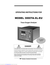
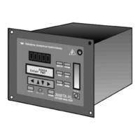
Teledyne 3000TA-XL-EU Operating Instructions Manual (108 pages)
Trace Oxygen Analyzer
Brand:
Teledyne
| Category:
Analytical Instruments
| Size: 2.39 MB
Table of Contents
Safety Messages
6
Table of Contents
9
Introduction
17
Overview
17
Typical Applications
17
Main Features of the Analyzer
17
Model Designations
18
Front Panel (Operator Interface)
19
Figure 1-1: Model 3000TA-XL-EU Front Panel
19
Rear Panel (Equipment Interface)
21
Figure 1-2: Model 3000TA-XL Rear Panel
22
Operational Theory
23
Introduction
23
Micro-Fuel Sensor
23
Principles of Operation
23
Anatomy of a Micro-Fuel Cell
24
Figure 2-1: Micro-Fuel Cell
24
Electrochemical Reactions
25
Figure 2-2: Cross Section of a Micro-Fuel Cell (Not to Scale)
25
The Effect of Pressure
26
Calibration Characteristics
26
Figure 2-3: Characteristic Input/Output Curve for a Micro-Fuel Cell
27
Sample System
28
Figure 2-4: Piping Layout
29
Figure 2-5A: Flow Diagram-Sample under Pressure-Standard
30
Figure 2-5C: Flow Diagram-Sample under Pressure-Model 3000TA-XL-CV
30
Electronics and Signal Processing
31
Figure 2-6: Power Supply and PCB Location
31
Figure 2-7: Block Diagram of the Model 3000TA-XL-EU Electronics
32
Installation
35
Unpacking the Analyzer
35
Mounting the Analyzer
35
Figure 3-1: Front Panel of the Model 3000TA-XL-EU
36
Figure 3-2: Required Front Door Clearance
36
Rear Panel Connections
37
Gas Connections
37
Figure 3-3: Rear Panel of the Model 3000TA-XL-EU
37
Electrical Connections
38
50-Pin Equipment Interface Connector
39
Analog Outputs
39
Figure 3-4: Equipment Interface Connector Pin Arrangement
39
Primary Input Power
39
Alarm Relays
40
Table 3-1: Analog Output Connections
40
Table 3-2: Alarm Relay Contact Pins
41
Cal Contact
42
Digital Remote Cal Inputs
42
Table 3-3: Remote Calibration Connections
42
Range ID Relays
43
Remote Calibration Protocol
43
Network I/O
44
Remote Valve Connections
44
Table 3-4: Range ID Relay Connections
44
Figure 3-5: Remote Probe Connections
45
Figure 3-6: FET Series Resistance
45
Port
46
Table 3-5: Commands Via RS-232 Input
46
Table 3-6: Required RS-232 Options
46
Installing the Micro-Fuel Cell
47
B-2CXL Micro-Fuel Cell
47
Insta-Trace Micro-Fuel Cell
48
Figure 3-7: Installing the B-2CXL MFC (Other Cells Similar)
48
Testing the System
50
Figure 3-8: Installing the Insta-Trace Micro-Fuel Cell
50
Operation
53
Introduction
53
Using the Data Entry and Function Buttons
54
Figure 4-1: Hierarchy of Available Functions
55
The System Function
56
Tracking the Oxygen Readings During Calibration and Alarm Delay
57
Setting up an Auto-Cal
58
Password Protection
59
Entering the Password
59
Installing or Changing the Password
60
Logout
62
System Self-Diagnostic Test
63
Version Screen
64
Calibration of the Analyzer
64
Zero Cal
65
Auto Mode Zeroing
65
Manual Mode Zeroing
66
Cell Failure
67
Span Cal
67
Auto Mode Spanning
67
Manual Mode Spanning
68
Span Failure
69
Switching of Sample Streams
70
Special Notes on Hydrogen Gas Stream
70
The Alarms Function
71
The Range Function
73
Setting the Analog Output Ranges
74
Fixed Range Analysis
74
The Analyze Function
75
Signal Output
75
Table 4-1: Output Signals
76
The IP Address Function
77
Table 4-2: Range ID Output Voltage
77
Web Implementation
79
The Embedded Browser
79
Figure 5-1: Analyzer Status Window-Running
80
Remote Calibration
81
Remote Span
81
Figure 5-2: Span Calibration Window
82
Remote Zero
83
Figure 5-3: Zero Calibration Window
83
Set the Alarms Remotely
84
Set the Ranges Remotely
85
Figure 5-5: Set Range Window
85
System Menu
86
Figure 5-6: System Window
86
The Self-Test Function
87
Figure 5-7: Self-Test Window
87
Maintenance
89
Routine Maintenance
89
Cell Replacement
89
Storing and Handling Replacement Cells
89
When to Replace a Cell
90
Removing the Micro-Fuel Cell
91
Installing a New Micro-Fuel Cell
91
Figure 6-1: Removing the Micro-Fuel
92
Cell Warranty
93
Figure 6-2: Installing the Insta-Trace Cell
93
Fuse Replacement
94
Figure 6-3: Removing Fuse Block from Housing
94
System Self Diagnostic Test
95
Figure 6-4: Installing Fuses
95
Table 6-1: Self Test Failure Codes
95
Major Internal Components
96
Figure 6-5: Rear Panel Removal
96
Cleaning
97
Troubleshooting
97
Appendix
99
Specifications
99
Recommended 2-Year Spare Parts List
101
Drawing List
102
19-Inch Relay Rack Panel Mount
102
Figure A-1: Single and Dual 19" Rack Mounts
102
Application Notes
103
Material Safety Data Sheet
105
Advertisement
Teledyne 3000TA-XL-EU Quick Start Manual (18 pages)
Teledyne Trace Oxygen Analyzer Quick Start Guide
Brand:
Teledyne
| Category:
Analytical Instruments
| Size: 0.88 MB
Table of Contents
Getting Started
3
Front Panel (Operator Interface)
3
Rear Panel (Equipment Interface)
5
Setup and Install
6
Electrical Connections
7
Basic Operation
10
Default Configuration
10
Using the Data Entry and Function Buttons
10
Available Functions
11
Password Protection
12
Entering the Password
12
Calibration of the Analyzer
13
Zero Calibration
13
Span Calibration
14
Setting Alarm Parameters
15
The Analyze Function
17
Advertisement
Related Products
Teledyne 3000TA
Teledyne 3000TB
Teledyne 3000MA
Teledyne 3000MB
Teledyne 3000PA
Teledyne 3000PB
Teledyne 3000ZA-3X
Teledyne 3000ZA
Teledyne 3000ZA2G
Teledyne 3000PA-EU
Teledyne Categories
Measuring Instruments
Analytical Instruments
Digital Camera
Test Equipment
Laboratory Equipment
More Teledyne Manuals
Login
Sign In
OR
Sign in with Facebook
Sign in with Google
Upload manual
Upload from disk
Upload from URL