Sign In
Upload
Manuals
Brands
Samsung Manuals
Air Conditioner
DVM Series
Samsung DVM Series Manuals
Manuals and User Guides for Samsung DVM Series. We have
2
Samsung DVM Series manuals available for free PDF download: Service Manual, Installation Manual
Samsung DVM Series Service Manual (391 pages)
SYSTEM AIR CONDITIONER
Brand:
Samsung
| Category:
Air Conditioner
| Size: 49.23 MB
Table of Contents
Table of Contents
1
Precautions
2
Numbering System of Model
3
Outdoor Unit
4
Indoor Unit Version
5
1-Way Cassette Type (K)
5
4-Way Cassette Type (C)
5
Duct Type (Low Silhouette: D)
6
Duct Type (High Pressure: H)
6
Duct Type (Low Pressure: L)
6
Duct Type (Built-In: B)
6
Wall Mounted Type (W)
7
Floor Standing Type (P)
7
Outdoor Unit Version
7
Accessories (Options)
8
Numbering System of Model Classification
9
Combination
13
Cooling Only
13
Heat Pump
15
Indoor Unit
17
1-Way Cassette Type
19
50Hz
19
Product Specification
19
60Hz
20
4-Way Cassette Type
21
Duct Type (Low Silhouette)
27
Duct Type (Built-In)
29
Duct Type (High Pressure)
33
Duct Type (Low Pressure)
35
Wall-Mounted Type
37
Floor Standing Type
41
Ceiling Type
43
Outdoor Unit 50Hz
45
Outdoor Unit 60Hz
51
Classification of Outdoor Unit
53
Installation
53
The Option Set Part of Outdoor Unit PCB
55
The Setting of Outdoor Unit Option Switch and Key Function
55
The Setting of Option Switch
55
The Setting Switch of Indoor Unit Installation Number
56
The Display Method of English Characters and Figures on PCB Display Part
56
The Function of Key on the Outdoor Unit PCB
57
A, C, D, B, E Type Outdoor Unit
57
Display Part
57
Key Function
57
View Mode (B, E Type Outdoor Unit)
58
The Setting of Option Switch (F, G Type Outdoor Unit)
59
The Option Set Part of Outdoor PCB
59
Operation Control Key and Display Part
60
Main Operation Mode and Function
60
View Mode
61
The Setting of Option Switch of Outdoor Unit
62
The Setting of Indoor Address
63
Main Address Setup
64
RMC Address Setup
64
The Indoor Unit Option Switch Setup
65
Pre-Check for the Test Operation
66
Check the Indoor and Outdoor Unit Power Cable, and Communication Wire
66
Preheat the Compressor Crankcase Heater by Turning Power Breaker (3 Phases & Single Phase) on before 6 Hours to Test Operation
66
Check the Power between the Outdoor Unit and the Cabinet Panel
66
The Outdoor Unit Starts a Tracking to Check the Connected Indoor Unit and Option at Power on
67
Check the System Pressure by Use of Manifold Gauge
67
Prepare to Check the Test Operation with S-NET Measurement Instrument
68
Test Operation
69
The Cooling Test Operation by S-NET
71
The Heating Test Operation by S-NET
73
Installation of Air Conditioner
74
Precautions for Installation
74
Installing Order and Method
74
Disassembly and Reassembly 1-Way Cassette Type
77
Disassembly and Reassembly 4-Way Cassette Type
86
Disassembly and Reassembly Duct Type (Low Silhouette)
95
Disassembly and Reassembly Duct Type (High Pressure-Old Type)
101
Disassembly and Reassembly Duct Type (High & Low Pressure-New Type)
105
Disassembly and Reassembly Duct Type (Built-In)
108
Disassembly and Reassembly Wall-Mounted Type
114
Disassembly and Reassembly Floor Standing Type
116
Disassembly and Reassembly Ceiling Type
126
Disassembly and Reassembly B Type
135
Disassembly and Reassembly D Type
137
Disassembly and Reassembly E Type
139
Disassembly and Reassembly F Type
141
Disassembly and Reassembly G Type
143
Refrigerating Cycle Diagram-Cooling Only
145
Main Parts Status
147
Refrigerating Cycle Diagram-Heat Pump
148
Refrigerating Cycle Diagram-RMAH 140/160
150
Outdoor Unit (Main)
150
Refrigerating Cycle Diagram-RMAH 180/200
151
Refrigerating Cycle Diagram-RMAH 220/240/260
152
Refrigerating Cycle Diagram-RMAH 280/300
153
PCB Option Code Input Method (Example: 021E31142285)
157
Set up the Model Option
157
Option Code
162
Operation Flow of Outdoor Unit
165
Troubleshooting
165
Initial Tracking (Communication Check)-E2 Indicated if Abnormal
166
Reverse Phase/Missing Phase Detection-P4 Indicated if Abnormal
168
To Check the Power to be Used for 3 Phase Power Compressor if the Power Is on
168
Compressor Preheating-Ch Indicated
169
Self-Diagnosis by the Outdoor Unit Error Display
170
High Temperature of Discharge Sensor
172
High Temperature of COND Sensor
173
COND down Due to the SUMP Control
174
Low Pressure Switch Detection
175
Reverse Phase Detection of 3 Phase Power
176
Freezing of Heat Exchanger
177
Momentary Power Failure
178
Protection of High Pressure Sensor
178
Protection of Low Pressure Sensor
178
In Removing Frost
179
Protection Control of Condensation Ratio
179
Outdoor Temperature Sensor Error
180
Outdoor Unit Heat Exchanger Temperature Sensor Error (Open/Short)
181
Discharge Temperature Sensor Error (Open/Short)
182
COND out Temperature Sensor Error (Open/Short)
183
Oil Temperature Sensor Error (Open/Short)
184
Suction Temperature Sensor Error (Open/Short)
185
Low Pressure Sensor Error (Open/Short)
186
Detection of High/Low Pressure Sensor Error
186
High Pressure Sensor Error (Open/Short)
186
Fixed Compressor Discharge Temperature Sensor Error (Open/Short)
187
Communication Error after Completion of Tracking
188
Communication Error in Tracking
189
Indoor Unit Float Switch Error
190
Setting Error of Option Switch in Indoor Unit
192
Breakaway of Indoor Unit EVAP in Sensor
193
Breakaway of Indoor Unit EVAP out Sensor
194
Electronic Expansion Valve Open Error
195
Electronic Expansion Valve Close Error
196
Breakaway of EVAP IN, out Sensors
197
Total Leakage of Outdoor Refrigerant/Loading Failure
198
Breakaway of Outdoor Unit COND Sensor
200
Breakaway of Oil Temperature Sensor
201
Breakaway of Suction Temperature Sensor
201
Breakaway of Fixed Compressor Discharge Sensor
202
Indoor Unit Room Sensor Error (Open/Short)
203
Indoor Unit EVAP in Sensor Error (Open/Short)
204
Indoor Unit EVAP out Sensor Error (Open/Short)
205
Indoor Unit Fan Motor Starting Error
206
No Cooling Operation
206
No Heating Operation
206
Outdoor Unit Display at the Detection of an Error
207
Indoor Unit Room Temp. Sensor Error (Open/Short)
211
Indoor Unit EVAP out Sensor Error (Open/Short) Troubleshooting
213
Indoor Unit EVAP in Sensor Breakaway
214
Indoor Unit EVAP out Sensor Breakaway
215
The Starting Error of Indoor Unit Fan Motor
216
Communication Error between the Indoor Unit and Outdoor Unit on Tracking
217
Communication Error after the Completion of Tracking
218
Outdoor Temperature Sensor Error Troubleshooting
219
Outdoor COND out Sensor Error (Open/Short)
220
COND out Sensor Breakaway
221
The Error of Outdoor Unit COND MID Temperature Sensor (Open/Short)
222
The Error of Digital Compressor Discharge Temperature Sensor (Open/Short)
223
The Error of Fixed Capacity Compressor Discharge Temperature Sensor Error (Open/Short)
224
The Compressor Discharge Temperature Sensor Breakaway
225
The Compressor SUMP Temperature (Oil Temperature) Sensor Breakaway
226
OIL Temperature Sensor Error (Open/Short) Troubleshooting
227
High Pressure Sensor Error (Open/Short) Troubleshooting
228
Low Pressure Sensor Error (Open/Short) Troubleshooting
228
Suction Temperature Sensor Error (Open/Short) Troubleshooting
229
Indoor Unit Freezing Protection
230
High Pressure Protection Control
231
Low Pressure Protection Control
232
Compressor SUMP Temperature Protection
233
The Reverse Phase of 3 Phases Power
234
Compression Rate Control
235
Prohibit to Start Compressor According to the Outdoor Temperature
236
The Low Pressure Detection Error at the Initial of Compressor Start
237
Defrost Operation
238
Low Discharge Pressure Control
238
Oil Leveling
238
Loading Failure or OLP TRIP
239
Oil Collection Operation
241
Setting Error of Option Switch for Peripheral Equipment Control
242
Floating Switch Detection of the Indoor Unit Drain Pump
243
Indoor Unit EEV CLOSE Error
245
Indoor Unit EEV OPEN Error
246
Self-Diagnosis by LED Indoor Unit
247
Defect Judgment and Troubleshooting by S-NET
248
S-NET Main Operation Check
248
Outdoor Unit Troubleshooting
249
Indoor Unit Troubleshooting
251
S-NET Defect Type and Check Method
254
System Refrigerant over Charge
254
System Refrigerant Shortage
255
Indoor Unit PCB Defect/Sensor Defect
256
EEV Defect/Pipe Clogging
257
The Mixing up Communication Wires between Outdoor Units
258
No Driving of Outdoor Unit Fan/Clogging of the Surroundings of Outdoor Unit Heat Exchanger
259
Clogging of the Refrigerant Pipe of Sensor Attaching Part at the Indoor Unit Inlet/Department of a Sensor
260
Breakaway of an Outlet Sensor of Indoor Unit
261
Breakaway of PWM Valve Connecter (Not Controlled the Capacity of Compressor)/Shortage of Refrigerant
262
Full Leakage of Refrigerant/Loading Defect
263
Outdoor Temperature Sensor Open
264
Outdoor Unit Cond MID Sensor Open
265
Outdoor Unit Cond out Sensor Open
266
Department of the Connecter of Outdoor Unit Temperature Sensor
267
Outdoor Unit Discharge Temperature Sensor OPEN
268
Outdoor Unit Exploded View
269
B Type Exploded View
269
Exploded Views and Parts List
269
B Type Part List
270
D Type Exploded View
271
D Type Part List
272
E Type Exploded View
275
E Type Part List
276
F Type Exploded View
279
F Type Part List
282
G Type Exploded View
286
G Type Part List
288
DVM Plus (RMBH100GAM0)
303
DVM Plus Part List
304
Indoor Unit Exploded View
305
1-Way Cassette Type (Body) Exploded View
305
1-Way Cassette Type (Body) Part List
306
1-Way Cassette Type (Panel) Exploded View
309
1-Way Cassette Type (Panel) Part List
310
4-Way Cassette Type (Body: 5.2Kw-7.2Kw) Exploded View
311
4-Way Cassette Type (Body: 5.2Kw-7.2Kw) Part List
312
4-Way Cassette Type (Body: 10.5Kw) Exploded View
315
4-Way Cassette Type (Body: 10.5Kw) Part List
316
4-Way Cassette Type (Panel) Exploded View
317
4-Way Cassette Type (Panel) Part List
318
4-Way Cassette Type (Body: 5.2Kw-14Kw) Exploded View
319
4-Way Cassette Type (Body: 5.2Kw-14Kw) Part List
320
Duct Type (Low Silhouette) Exploded View
325
Duct Type (Low Silhouette) Part List
326
Duct Type (Built-In: 2.0Kw-4.0Kw) Exploded View
331
Options
331
Duct Type (Built-In: 2.0Kw-4.0Kw) Part List
332
Duct Type (Built-In: 5.2Kw-7.2Kw) Exploded View
335
Duct Type (Built-In: 5.2Kw-7.2Kw) Part List
336
Duct Type (High Pressure) Exploded View
337
Duct Type (High Pressure) Part List
338
Duct Type (High-Low Pressure) Exploded View
339
Duct Type (High-Low Pressure) Part List
340
Wall-Mounted Type (2.0Kw-4.0Kw) Exploded View
341
Wall-Mounted Type (2.0Kw-4.0Kw) Part List
342
Wall-Mounted Type (5.0Kw-7.2Kw) Exploded View
345
Wall-Mounted Type (5.0Kw-7.2Kw) Part List
346
Floor Standing Type Exploded View
347
Floor Standing Type Part List
348
Floor Standing Type (Ass'y Panel Outlet) Exploded View
349
Floor Standing Type (Ass'y Panel Outlet) Part List
350
Floor Standing Type (Ass'y Shutter) Exploded View
351
Floor Standing Type (Ass'y Shutter) Part List
352
Floor Standing Type (Ass'y Inlet) Exploded View
353
Floor Standing Type (Ass'y Inlet) Part List
354
Ceiling Type Exploded View
355
Ceiling Type Part List
356
Indoor Unit Wiring Diagram
359
1-Way Cassette Type Diagram
359
Cooling Only (AVMKC)
359
Heat Pump (AVMKH)
360
4-Way Cassette Type Diagram
361
Cooling Only (AVMCC)
361
Heat Pump (AVMCH)
362
Duct Type Diagram
363
Low Silhouette & Built-In-Cooling Only (AVMDC/AVMBC)
363
Low Silhouette & Built-In-Heat Pump (AVMDH/AVMBH)
364
Low Pressure (AVMHC/AVMHH/AVMLC/AVMLH)
365
Wall-Mounted Type(AVMWC/AVMWH) Diagram
366
Ceiling Type (AVF) Diagram
367
Cooling Only Diagram
368
050/060/072 Diagram
368
070F Diagram
369
080/100 Diagram
370
100F Diagram
371
Heat Pump Diagram
372
050/060 Diagram
372
RMAH140/160/180/200 Diagram
375
RMAH200/240/260/280/300 Diagram
376
AVMKC(H) Schematic Diagram
377
1-Way Cassette Type Schematic Diagram
377
Outdoor Unit Schematic Diagram
377
4-Way Cassette Type Schematic Diagram
378
Avmcc(H)
378
Duct Type Schematic Diagram
379
AVMDC(H)/AVMBC(H)/AVMHC(H) Schematic Diagram
379
AVMWC(H)052/072 Schematic Diagram
380
Wall-Mounted Type Schematic Diagram
381
AVMWC(H)020/032/040 Schematic Diagram
381
Floor Standing Type Schematic Diagram
382
AVMPC(H) Schematic Diagram
382
Ceiling Type Schematic Diagram
383
Cooling Only Schematic Diagram
384
060/070 Schematic Diagram
384
050 Schematic Diagram
385
Heat Pump Schematic Diagram
386
050/060 Schematic Diagram
386
080/100 Schematic Diagram
387
RMAH Schematic Diagram
388
Advertisement
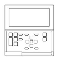
Samsung DVM Series Installation Manual (31 pages)
DVM Hydro unit / Hydro unit HT Wired Remote Control
Brand:
Samsung
| Category:
Remote Control
| Size: 5.67 MB
Table of Contents
Installation Manual
1
Safety Information
2
Wired Remote Controller Installation
4
Accessories
4
External Dimensions
4
Tracking Hydro Unit/Hydro Unit HT from a Wired Remote Controller
8
Individual Control with Your Wired Remote Controller
9
Group Control with Your Wired Remote Controller
10
Controlling 2-Remote Controller
11
Sharing the Temperature of Hot Water Tank Sensor
12
Connecting One Wired Remote Controller
12
Connecting 2 or more Wired Remote Controller
13
Initializing Your Wired Remote Controller Communication
14
Error Display on the Wired Remote Controller
14
Wired Remote Controller Error Code
15
Use of Wired Remote Controller Installation / Service Mode
16
Use of Wired Remote Controller
18
Use of User Setting Mode
18
Field Specification Setting Mode of Wired Remote Controller
20
Functions that Requires Setting According to Field Specification
24
Self-Test Mode of Wired Remote Controller
28
Advertisement
Related Products
Samsung DVM S ECO AM XMDG Series
Samsung DVM S ECO BIG Series
Samsung DVM S WATER-GEO
Samsung DVM S Series
Samsung DVM S AM FXVAGR Series
Samsung DVM S AM HXVAGH Series
Samsung DVM S AM FXVAGH Series
Samsung DVM S AM MXV NR Series
Samsung DVM S AM MXVAJC Series
Samsung DVMS HP
Samsung Categories
Cell Phone
Monitor
Microwave Oven
LCD TV
Air Conditioner
More Samsung Manuals
Login
Sign In
OR
Sign in with Facebook
Sign in with Google
Upload manual
Upload from disk
Upload from URL