Sign In
Upload
Manuals
Brands
Paradise Datacom Manuals
Amplifier
HPAKU3080AC Series
Paradise Datacom HPAKU3080AC Series Manuals
Manuals and User Guides for Paradise Datacom HPAKU3080AC Series. We have
1
Paradise Datacom HPAKU3080AC Series manual available for free PDF download: Operation Manual
Paradise Datacom HPAKU3080AC Series Operation Manual (82 pages)
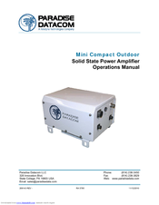
Mini Compact Outdoor Solid State Power Amplifier
Brand:
Paradise Datacom
| Category:
Amplifier
| Size: 1.41 MB
Table of Contents
Table of Contents
3
Section 1: General Information
9
Specifications
9
Equipment Supplied
10
Inspection
10
Safety Considerations
10
High Voltage Hazards
10
RF Transmission Hazards
10
1 Introduction
9
Description
9
Section 2: Installation
13
2 Introduction
13
Dimensions and Weight
13
Figure 2-1: Outline Drawing, Ku-Band Mini Compact Outdoor SSPA
13
Connector Pin-Outs
14
RF in (J1) [Type N (F)]
14
RF out (J2)
14
Table 2-1: Unit Weights (Typical)
14
RF Output Sample Port (J3) [Type N (F)]
15
Monitor & Control Port (J4) [MS3112E18-32S]
15
Alarms on J4
15
Auxiliary Alarm (J4) Form C Contacts
15
Open Collector Alarm Outputs (J4)
15
Summary Alarm (J4) Form C Contacts
15
Table 2-2: J4 Monitor & Control Port Pin-Outs
16
Serial I/O Control (J4)
17
Link Port (J5) [MS3112E10-6S]
17
Switch Port (J6) [MS3112E10-6S]
17
Table 2-3: J5 Link Port Pin-Outs
17
Table 2-4: J6 Switch Port Pin-Outs
17
AC in (J7) [MS3102R16-10P]
18
Auxiliary Power Port (J8) [MS3112E10-6S]
18
Table 2-5: J7 AC in Port Pin-Outs
18
Table 2-6: Power Requirements
18
Table 2-7: J8 Auxiliary Power Port Pin-Outs
18
Chassis Ground Pin
19
Physical Features
19
Summary Alarm Indicator
19
Removable Fan Tray
19
Figure 2-2: Mini Compact Outdoor SSPA Air Flow
19
Installation
20
Safety Considerations
20
Inspection
20
Table 2-8: Universal CO Mounting Kit Parts List
20
Installation
21
Figure 2-3: Attach Mounting Supports to Unit
21
Figure 2-4: Install All-Thread Stud
21
Figure 2-5: Mount Unit to Antenna Boom
22
Section 3: Quick Start
23
3 Introduction
23
Figure 3-1: J4 Connections for Ethernet Communications, Default IP Address
23
Figure 3-2: J4 Connections for Ethernet Communications, User-Defined IP Address
23
Remote Communications Connections
23
Figure 3-3: J4 Connections for RS-485 Communications
24
Figure 3-4: J4 Connections for RS-232 Communications
24
Figure 3-5: Ethernet Quick Start Cable, 207755 (Revision a and Beyond)
24
Quick Start Cables
24
Quick Start Operation
25
Figure 3-6: RS232 Quick Start Cable, 207988
25
Set PC Configuration
25
Quick Start Ethernet Connection
26
Quick Start RS-232 Connection
27
Figure 3-7: Universal M&C Add Unit Menu
28
Figure 3-8: Add Compact Outdoor SSPA Window, Via Serial (Left) or Internet (Right)
28
Universal M&C Status Window
29
Figure 3-9: Universal M&C Status Window
29
Signal Indicators
29
Fault Status Indicators
30
Gain Adjustment
31
Reference Source
31
RF Power Indicator
31
Voltage, Current and Temperature Display
31
Figure 3-10: Universal M&C, Settings
32
Universal M&C Settings Window
32
Figure 3-11: Spare Fault Wizard
33
Figure 3-12: Universal M&C, IP Setup
34
IP Setup
34
Figure 3-13: Preferences Window
35
Figure 3-14: Example, Log Entry
35
Universal M&C Preferences
35
Universal M&C Operation
28
Figure 3-15: Enter IP Address for Mini Compact Outdoor SSPA (Default Is 192.168.0.9)
36
Figure 3-16: M&C Applet Loading into Browser Window
36
Figure 3-17: Enter Password (Default Is "Paradise")
37
Figure 3-18: Status and Faults Window Descriptions
37
Navigating the Web M&C
37
Figure 3-19: Communication Settings Window Descriptions
38
Figure 3-20: General Settings Window Descriptions
39
Figure 3-21: Fault Settings Window Descriptions
40
Web-Based M&C
36
Section 4: L-Band Operation
41
4 Block up Converter Overview
41
Figure 4-1: Configurator, Compact Outdoor SSPA, BUC Options
41
Converter Features
42
Figure 4-2: Compact Outdoor Block Diagram of BUC / SSPA System
42
Table 4-1: BUC Frequency Specifications
42
Smart Reference Technology
43
Table 4-2: BUC RF Output Phase Noise Specification
43
Theory of Operation
43
FSK Monitor and Control
44
Figure 4-3: Mini Compact Outdoor SSPB with PD25 Evolution Modem
45
IFL Cable Considerations
45
Table 4-3: Common Coaxial Cable Characteristics
45
Typical System Configuration
45
Section 5: Performance Tests
47
5 Introduction
47
Standard Tests
47
Swept Gain
47
Figure 5-1: Spurious and Gain Data
47
Spurious
48
Input Return Loss
48
Output Return Loss
48
Figure 5-2: Return Loss, Intermodulation and Phase Noise Data
48
Intermodulation Distortion
49
Power Requirements
49
Figure 5-3: M&C, Output Power, Ground, Phase Lock and Misc. Data
49
Earth Ground
50
Sample Port
50
P and P
50
I/O Test
50
Ethernet
50
Tests for Units with Integrated BUC
51
Fsk
51
Microphonics
51
Phase Noise
51
Reference Lock
51
Am/Pm
52
Group Delay
52
Harmonics
52
Noise Figure
52
Noise Power
52
Optional Tests
52
Section 6: Maintenance and Troubleshooting
53
6 Introduction
53
Cooling System Maintenance
53
Fan Removal and Heatsink Cleaning
53
Fan Replacement
53
Troubleshooting Guide
54
Unit Doesn't Power up
54
Unit Powers On, LED Lamp Glows Red
54
SSPA Unit Powers Up, LED Lamp Glows Green, no RF Output Present
54
Cannot Connect to SSPA through Remote Control Interface
54
The FSK Link between a Modem and the SSPB Unit Is Not Working
55
Section 7: Redundant System Operation
57
7 Redundant System Concepts
57
1:1 Redundant Systems
57
Figure 7-1: 1:1 Redundant System with Input Coaxial Switch and Output Waveguide Switch
57
Figure 7-2: 1:1 Redundant System with Input Splitter Substituted for Input Switch
57
1:2 Redundant Systems
58
Figure 7-3: 1:1 Redundant System with L Band Input
58
Figure 7-4: 1:2 Redundant System Block Diagram
58
Section 8: Remote Control Interface
59
8 Serial Protocol Overview
59
Figure 8-1: Compact Outdoor Remote Control Interface Stack
59
Table 8-1: Interface Selection
60
Serial Communication
61
Header Packet
61
Destination Address
61
Figure 8-2: Basic Communication Packet
61
Figure 8-3: Header Sub-Packet
61
Frame Sync Word
61
Source Address
62
Data Packet
62
Command
62
Figure 8-4: Data Sub-Packet
62
Protocol ID
62
Request ID
62
Data Tag
63
Table 8-2: Command Byte Values
63
Table 8-3: Data Tag Byte Values
63
Data Address / Error Status / Local Port Frame Length
64
Data Field
64
Data Length
64
Table 8-4: Error Status Bytes
64
Trailer Packet
65
Frame Check
65
Timing Issues
65
Figure 8-5: Trailer Sub-Packet
65
Serial Communications Protocol
66
Table 8-5: Request Frame Structure
66
Table 8-6: Response Frame Structure
66
Table 8-7: System Settings Data Values
67
Table 8-8: System Threshold Data Values
68
Table 8-9: System Condition Addressing
69
Ethernet Interface
70
Ipnet Interface
70
General Concept
70
Figure 8-6: UDP Redirect Frame Example
71
Table 8-10: OSI Model for Compact Outdoor SSPA Ethernet IP Interface
71
Setting Ipnet Interface
72
Troubleshooting IP Connectivity
72
Overview
70
SNMP Interface
73
SNMP MIB Tree
74
Description of MIB Entities
75
Table 8-11: Detailed Settings for Mini CO SSPA Mode (Device Type=8)
76
Table 8-12: Detailed Thresholds
78
Table 8-13: Detailed Conditions
78
Figure 8-7: Universal M&C, IP Setup Tab
79
Figure 8-8: Universal M&C, Settings Tab
79
Connecting to a MIB Browser
80
Figure 8-10: Getif Mbrowser Window, with Update Data in Output Data Box
80
Figure 8-9: Getif Application Parameters Tab
80
M&C Via SNMP
79
Appendix A: Documentation
81
Operations Manual, HPA3, Mini Compact Outdoor SSPA 208143 REV
81
Advertisement
Advertisement
Related Products
Paradise Datacom HPAKU3050AC Series
Paradise Datacom HPAK2010AC Series
Paradise Datacom HPAK2020AC Series
Paradise Datacom HPAK2050AC Series
Paradise Datacom HPAK2070AC Series
Paradise Datacom HPAK2100AC Series
Paradise Datacom HPAK2125AC Series
Paradise Datacom HPAKG200AC Series
Paradise Datacom HPAKA040AC Series
Paradise Datacom HPAKA080AC Series
Paradise Datacom Categories
Outdoor Light
Landscape Lighting
Light Fixture
Modem
Transformer
More Paradise Datacom Manuals
Login
Sign In
OR
Sign in with Facebook
Sign in with Google
Upload manual
Upload from disk
Upload from URL