Sign In
Upload
Manuals
Brands
JRC Manuals
Marine Radar
JMR-5410-4X
JRC JMR-5410-4X Manuals
Manuals and User Guides for JRC JMR-5410-4X. We have
5
JRC JMR-5410-4X manuals available for free PDF download: Instruction Manual, Simplified Instruction Manual
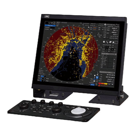
JRC JMR-5410-4X Instruction Manual (688 pages)
MARINE RADAR EQUIPMENT
Brand:
JRC
| Category:
Marine Radar
| Size: 19.17 MB
Table of Contents
Pictorial Indication
12
Table of Contents
35
Overview
55
Functions
56
Features
57
Components
60
Structure
66
General System Diagrams
90
Name and Function of each Unit
97
Name and Main Function of the Operation Unit
97
Standard Operation Unit
97
Display Unit
99
Names and Main Functions of the Mode Screen Common Sections
100
Menu] Button
100
Key Assignment Indication Area
101
Own Ship Information
101
Other Ship Information
104
Right Toolbar
105
Toolbar
106
Buttons that Are Normally Displayed
107
Buttons that Are Normally Hidden
107
Alert Notification Area
108
Other Common Area
108
Navigation Tools
109
Range and Mode Information
109
Radar Signal Information
110
Radar System Information
111
Display Inside the PPI
112
Common Information Window
113
Information Monitor Windows
114
Target INFO
114
TT List
116
AIS List
116
AIS Detail INFO
116
2Nd PPI
119
Wind/Current Block
119
Conning
120
Information Reference Windows
121
Switching between a Standard Window and an Extended Window
121
AIS MSG Tray
121
Navtex
122
Active Alert
124
Alert History
124
Maintenance INFO
124
Ais
125
Section 3 Common Basic Operations
127
Powering on and Starting
127
Starting each Mode
127
Basic Operations When Using a Trackball
128
Basic Trackball Operations
128
Basic Operations of Clicking, Right-Clicking and Double-Clicking
128
Displaying Simplified Information and Operational Guide of Objects
129
Cursor Types
129
Basic Menu Operations
131
Opening the Menu
131
Menu List
132
Closing the Menu
132
Basic Dialogue Box Operations
133
Changing Dialogue Box Settings
133
Closing a Dialogue Box
135
Title Bar
136
Operation of the Information Monitor Window
137
Opening the Information Monitor Window
137
Displaying an Information Monitor Window from Other than the [Page Selection] Dialogue Box
137
Confirming and Acknowledging an Alert
138
Stopping a Buzzer
139
Confirming Alert Contents
139
Acknowledging the Alert
140
Displaying Active Alert and Alert History
140
Switching the Day/Night Mode
142
Adjusting the Brightness of the Screen and Operation Unit
143
Display Brightness] Dialogue
143
Switching the Mode
144
Function Restriction by Mode
144
Mouseover Display
145
Condition and Timing of Mouseover Display
145
Starting Mouseover Display
145
Terminating Mouseover Display
145
How to Read Mouseover Display
146
MOB (man over Board)
147
Electronic Bearing Line (EBL) and Variable Range Marker (VRM)
148
Displaying the EBL and VRM Buttons
149
Basic Manipulation of EBL/VRM
149
Switching the Control Right of EBL/VRM
149
Setting up the Measurement Starting Points
150
Setting the EBL Bearing to True/Relative Display
150
Setting up the Range Unit of VRM
151
Operating the Intersecting Point between EBL and VRM
151
Rectangle Cursor
152
Cursor AUTO Mode
154
No Object
154
Ais
155
AZ) Acquisition/Activation Zone
156
AIS Filter
157
User Map
157
Non-Selected Object
157
Selected Object
158
Ebl
159
Vrm
159
EBL/VRM Intersecting Point
159
Monitoring Dragging Anchor
160
Object in the Unselected State
160
Selected State
160
Saving the Screen that Is Currently Displayed
161
Favourite" Registering Function
162
Registering/Cancelling Favourites
162
Calling a Favourite
162
MULTI] Dial
163
Functions of [MULTI] Dial
163
Functions Assigned to [MULTI] Dial
163
Displaying a Screen for Setting the Function that Is Assigned
163
Changing the Function that Is Assigned
163
Basic Operations of the Software Keyboard
164
Starting a Software Keyboard
164
Name and Function of each Section of the Keyboard
164
Setting a Date and a Time (Calendar Operation)
167
Details and Usage of a Calendar Picker and a Time Picker
167
Details of a Calendar
167
Help
168
Password Input
169
Managing Files with File Manager
170
File Management
170
Copying a File
171
Deleting a File
171
Loading and Saving Files
172
Loading Files
173
Unloading Data (Clearing Data from the Data Screen)
173
Saving Files
173
Using a Key Macro
174
Recording a Key Macro
174
Operate Remotely the Marine VHF Radiotelephone (JHS-800S)
175
Select VHF Radiotelephone (JHS-800S) for Use
175
Display VHF Radiotelephone Status from Menu-Bar
177
DSC Call for AIS Target on RADAR PPI
180
Returning to the Mode Selection Screen by Terminating Operation
182
Terminating this Equipment
182
Range and Bearing Measurement Methods
183
List of Measuring Tools
183
Target Position
184
Using the Cross-Hair Cursor
185
Displaying Information in the Cursor Information Readout Area
185
Measuring the Bearing and the Range from the Own Ship's Position to the Target by Using the Cross-Hair Cursor
186
Setting a Reference Point
188
Using the Range Rings
189
Using the Electronic Bearing Line (EBL) and Variable Range Marker (VRM)
190
Measuring a Range and a Bearing with EBL and VRM
190
Measuring a Range and a Bearing with the Trackball Section of the Operation Unit
190
Measuring with the [EBL] or [VRM] Dial on the Keyboard Operation Unit
191
Measuring between Arbitrary Two Points
193
Using Parallel Index Lines (PI)
195
Description of a Parallel Index Line
195
Displaying Parallel Index Lines
195
Displaying Parallel Index Lines by Using the [PI] Button on the Screen
195
Displaying Parallel Index Lines by Using the [PI] Key on the Operation Unit
196
Description of the [PI Menu] Dialogue
196
Setting All the Parallel Index Lines Concurrently (All Mode)
198
Changing the Bearing/Interval of Parallel Index Lines in the Operation Unit (All Mode)
199
Setting Parallel Index Lines Individually (Individual Mode)
200
Changing the Bearing/Interval/End Point of Parallel Index Lines in the Trackball Operation Unit (Individual Mode)
202
Displaying Lines at Equal Interval on the Left and Right Sides of the Own Ship's Position (Track Mode)
203
Changing the Bearing/Interval of Parallel Index Lines with the Trackball (Track Mode)
204
Displaying Two Intersecting Lines (Equiangular Mode)
205
Changing the Bearing of Two Intersecting Lines in the Trackball (Equiangular Mode)
206
Setting Parallel Index Lines in the Operation Unit
207
Operation in [All] Mode
207
Operation in [Individual] Mode
208
Operation in [Track] Mode
208
Operation in [Equiangular] Mode
209
Using the EBL Manoeuvre
210
Setting the Creation Conditions of the EBL Manoeuvre
210
Creating an EBL Manoeuvre Curve
211
Offsetting the Own Ship's Position Manually (Position Offset Function of Manual Position Fix)4-30
212
Position Offset] Tab of the [Manual Position Fix] Dialogue Box
212
Setting the Offset Amount that Is Input in the [Enter Offset] Dialogue as the Offset Position
213
Setting the Position on the Chart on Which the Mouse Button was Clicked as the Offset Position
213
Basic Operation of the Radar
215
Overview Flowchart
215
Starting and Shutting down the Radar
216
Powering on and Starting
216
Exiting Radar Operation
217
Observation Environment and Image Adjustment
218
Adjusting Screen Brightness
218
Changing the Observation Range
218
Adjusting Tune
219
Adjusting Gain
220
Rejecting Sea Clutter (Sea)
221
Rejecting Rain/Snow Clutter
223
Adjusting to Optimal Images (Selection of Observation Scenes)
225
General Radar Operation
227
Interference Rejection (IR Function)
227
Changing the Transmitter Pulse Length
228
Enhancing Targets
229
Using Video Processing (Echo Process)
230
Setting the Azimuth Mode
231
Setting a Motion Mode
233
Resetting Own Ship to Its Initial Position in [TM] (True Motion Display) Mode
234
Setting the Stabilisation Mode
235
Moving Own Ship's Display Position (off Centre)
235
Displaying Other Ship's Trails (Trails)
237
Trails Motion Mode
237
Changing Motion Mode of Trails
238
Setting the Length of the Trail
238
Clearing Trails Data
239
Doubling the Size of Radar Image
240
Hiding the Heading Line (HL OFF)
241
Hiding Graphics Information on Radar Display
242
Setting True Bearing
242
Setting Own Ship Speed
243
Switching Own Ship Speed Device
243
Entering the Ship's Heading/Own Ship's Speed Manually
243
Target Tracking and AIS
245
Restrictions
246
Collision Avoidance Issue (Explanation)
247
Collision Avoidance in Navigation
247
Marine Accidents and Collisions
247
Basic Concept of Collision Avoidance
248
Relative Vector and True Vector
249
Radar and Collision Avoidance
249
Displaying Symbols
250
Displaying/Hiding Target Tracking Symbols/Ais Target Symbols
250
Types and Definitions of Target Tracking Symbols
250
Types and Definitions of AIS Target Symbols
251
About AIS Aton (Aids to Navigation)
255
About AIS-SART Information
255
About Display Priority of AIS Targets
256
Switching between Ground Vector and Water Vector
256
Association Target Symbols
257
Preparation
258
Setting the Cursor Mode to AUTO Mode
258
Setting Vector
258
Vector Modes
258
Setting Vector Mode
259
Vector Length (Vector Time)
260
Setting the Vector Length
260
Setting Collision Decision Criteria
260
Setting CPA Limit
261
Setting TCPA Limit
261
Showing the CPA Ring
261
Setting and Operating Target Tracking
262
Acquiring Target
262
Automatic Acquisition (Automatic Acquisition) Mode
262
ACQ Manual (Manual Acquisition) Mode
263
Using Manual Acquisition and AUTO Acquisition Together
263
Setting up the Automatic Acquisition/ Activation Zone (AZ)
264
Using [New Target Warning] Dialogue Box in the [Alert] Menu
264
Using the Cursor
265
Using the EBL/VRM Dial for the Setting
265
Tracked Target Information Display
266
Erasing Unwanted Tracked Targets
267
Displaying Target ID no
268
Editing Tracked Target Properties
268
Adding Tracked Target ID Name
269
Setting Track Colour of Tracked Target
269
Setting Target for Which Ground Is Fixed to a Reference Target
270
Operation Test for Target Tracking
271
Test Video]
272
TT Simulator] (Target Tracking Simulator)
273
Gate Display]
274
Status] Display
274
Setting and Operating AIS
275
Enabling AIS Function
275
Activating AIS Targets (Activate AIS)
275
Manual Activation
275
Automatic Activation
276
Deactivating AIS Targets
276
Displaying AIS Information
277
Displaying Target ID no
281
Checking and Setting AIS Target Property
281
Setting Track Colour of AIS Target
281
Conditions for Deciding AIS Target to be Lost
282
Alert Display
283
Danger Target Alarm (CPA/TCPA)
284
Warning for New Target Acquired in Automatic Acquisition Guard Zone (New Target)
285
Lost Target Warning (Lost)
286
Target Tracking Function Alarm (TT Data)
287
Gyro Set Notification (Set Gyro)
287
Track Function
288
Setting the Past Position
288
Setting the Other Ship's Tracks
289
Setting Track Colour
289
Setting Other Ship's Track Colours
289
Turning On/Off Other Ship's Track Display
289
Setting up the Display Interval of Other Ship's Track
289
Clearing Other Ship's Track
289
Saving and Loading Other Ship's Track Data
289
Entering Own Ship's AIS Voyage Data
290
Editing and Sending AIS Messages
291
AIS Message Tray
293
Displaying the AIS Message Tray
293
Switching Message Display
294
Sending a Message in the Message Tray after Editing
294
Highlighting TT/AIS Symbols
295
Highlighting TT/AIS Symbols by Specifying Search Criteria
295
Highlighting AIS Symbols by List
296
Trial Manoeuvring
297
Outline of Trial Manoeuvring
297
Performing a Trial Manoeuvre
299
Displaying the TT/AIS Target List
300
TT List
300
AIS List
301
Confirming Own Ship's AIS Information
303
Displaying the Last Lost AIS Target
304
True and False Echoes on Display
305
Radar Wave with the Horizon
305
Intensity Reflected from the Target
307
Sea Clutter and Rain/Snow Clutter
308
Sea Clutter
308
Rain and Snow Clutter
309
Coping with Sea Clutter and Rain/Snow Clutter
310
False Echoes
311
Shadow
311
Side Lobe Effect
311
False Echo by Secondary Reflection
312
False Echo by Multiple Reflection
312
Second Time Echoes
313
Radar Interference
313
Radar Transponder (SART) Screen Display
314
Display of AIS-SART
316
Radar Screen Display Example
316
Numeric Data Display Example
316
Monitoring a Dragging Anchor
317
Setting a Dragging Anchor Monitoring Area
318
Setting a Dragging Anchor Monitoring Circle
318
Setting a Dragging Anchor Monitoring Polygon
318
Starting and Ending Dragging Anchor Monitoring
319
Starting Dragging Anchor Monitoring
319
Ending Dragging Anchor Monitoring
319
Moving/Editing/Deleting a Dragging Anchor Monitoring Area on the Chart
320
Moving a Dragging Anchor Monitoring Circle on the Chart
320
Moving a Dragging Anchor Monitoring Circle on the Context Menu
320
Moving a Dragging Anchor Monitoring Polygon on the Chart
320
Moving a Dragging Anchor Monitoring Ploygon on the Context Menu
321
Changing a Size of a Dragging Anchor Monitoring Circle on the Chart
321
Changing a Size of a Dragging Anchor Monitoring Circle on the Context Menu
321
Changing a Shape of a Dragging Anchor Monitoring Polygon on the Chart
322
Changing a Shape of a Dragging Anchor Monitoring Polygon on the Context Menu
322
Chart
325
Common
325
Special Line
325
Managing Special Line Data
325
C-Map Max
326
Warning Screen
326
C-MAP Cartridge Information
327
Contents of C-MAP Cartridge Information
327
Cartridge Code
327
Area Code
328
Searching for a Port or Service
329
Pick Report (C-MAP MAX)
330
Newpec
331
Warning Screen
331
Managing the Newpec Chart
332
Pick Report (Newpec)
332
Creating a User Map
333
Display the "User Map" Menu
334
Creating/Editing a User Map
335
Displaying the File Operation Dialogue
336
File Operation] Dialogue
336
Creating a New User Map
337
Editing the Existing User Map
337
Editing the User Map that Is Currently Displayed
337
Displaying a User Map
337
Operating a User Map File
338
Deleting a User Map File
338
Copying a User Map File
338
Merging Multiple User Map Files
338
Managing/Editing an Object [Mark/Line List]
339
Displaying a User Map List
339
Copying an Object
339
Deleting an Object
339
Bulk Deletion of Objects [Delete by Type/Colour]
340
Using Map Creation Tools
341
User Map Information Bar
341
Drawing Toolbar
341
Selecting an Object Type
342
Selecting a Colour of an Object
342
Creating an Object in the EBL/VRM Mode
343
Creating an Object by Specifying Latitude and Longitude
343
Creating an Object of Mark/Text
343
Creating an Object of Line
343
Deleting an Object
344
Object Property Dialogue
344
Selecting an Object
344
Setting a Comment
344
Changing an Object Display Scale Range
345
Moving an Object
345
Creating an Object
346
Creating a Mark (Mark Object)
347
Creating an Object by Specifying the Latitude and Longitude
347
Creating an Object with EBL/VRM Operation
348
Creating a Line (Line Object)
349
Advertisement
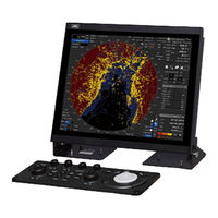
JRC JMR-5410-4X Instruction Manual (640 pages)
Brand:
JRC
| Category:
Marine Radar
| Size: 13.91 MB
Table of Contents
Preface
3
Pictorial Indication
13
Table of Contents
35
Precautions Upont Equipment Operation
53
Overview
53
Functions
54
Features
55
Components
58
Structure
63
General System Diagrams
85
Name and Function of each Unit
91
Name and Main Function of the Operation Unit
91
Standard Operation Unit
91
Display Unit
93
Names and Main Functions of the Mode Screen Common Sections
94
Menu] Button
94
Key Assignment Indication Area
95
Own Ship Information
95
Other Ship Information
98
Right Toolbar
99
Toolbar
100
Buttons that Are Normally Displayed
101
Buttons that Are Normally Hidden
101
Alert Notification Area
102
Other Common Area
102
Navigation Tools
103
Range and Mode Information
103
Radar Signal Information
104
Radar System Information
105
Display Inside the PPI
106
Common Information Window
107
Information Monitor Windows
108
Target INFO
108
AIS Detail INFO
110
AIS List
110
TT List
110
2Nd PPI
113
Wind/Current Block
113
Conning
114
Information Reference Windows
115
AIS MSG Tray
115
Switching between a Standard Window and an Extended Window
115
Navtex
116
Active Alert
118
Ais
118
Alert History
118
Section 3 Common Basic Operations
119
Powering on and Starting
119
Starting each Mode
119
Basic Operations When Using a Trackball
120
Basic Trackball Operations
120
Basic Operations of Clicking, Right-Clicking and Double-Clicking
120
Displaying Simplified Information and Operational Guide of Objects
121
Cursor Types
121
Basic Menu Operations
123
Opening the Menu
123
Menu List
124
Closing the Menu
124
Basic Dialogue Box Operations
125
Changing Dialogue Box Settings
125
Closing a Dialogue Box
126
Title Bar
127
Operation of the Information Monitor Window
128
Opening the Information Monitor Window
128
Displaying an Information Monitor Window from Other than the [Page Selection] Dialogue Box
128
Confirming and Acknowledging an Alert
129
Stopping a Buzzer
130
Confirming Alert Contents
130
Acknowledging the Alert
131
Displaying Active Alert and Alert History
131
Switching the Day/Night Mode
133
Adjusting the Brightness of the Screen and Operation Unit
134
Display Brightness] Dialogue
134
Switching the Mode
135
Function Restriction by Mode
135
Mouseover Display
136
Condition and Timing of Mouseover Display
136
Starting Mouseover Display
136
Terminating Mouseover Display
136
How to Read Mouseover Display
137
MOB (man over Board)
138
Electronic Bearing Line (EBL) and Variable Range Marker (VRM)
139
Displaying the EBL and VRM Buttons
140
Basic Manipulation of EBL/VRM
140
Switching the Control Right of EBL/VRM
140
Setting the EBL Bearing to True/Relative Display
141
Setting up the Measurement Starting Points
141
Operating the Intersecting Point between EBL and VRM
142
Setting up the Range Unit of VRM
142
Rectangle Cursor
143
Cursor AUTO Mode
145
No Object
145
Ais
146
AZ) Acquisition/Activation Zone
147
AIS Filter
148
User Map
148
Non-Selected Object
148
Line (Midpoint
149
Line (Select All
149
Mark
149
Selected Object
149
Ebl
150
Vrm
150
EBL/VRM Intersecting Point
150
Monitoring Dragging Anchor
151
Dragging Anchor Monitoring Circle (Circumference
151
Dragging Anchor Monitoring Circle (Square of the Four Corners
151
Dragging Anchor Monitoring Polygon (Line Segment
151
Dragging Anchor Monitoring Polygon (Vertex
151
Object in the Unselected State
151
Selected State
151
Saving the Screen that Is Currently Displayed
152
Favourite" Registering Function
153
Registering/Cancelling Favourites
153
Calling a Favourite
153
MULTI] Dial
154
Functions of [MULTI] Dial
154
Functions Assigned to [MULTI] Dial
154
Changing the Function that Is Assigned
154
Displaying a Screen for Setting the Function that Is Assigned
154
Basic Operations of the Software Keyboard
155
Starting a Software Keyboard
155
Name and Function of each Section of the Keyboard
155
Setting a Date and a Time (Calendar Operation)
158
Details and Usage of a Calendar Picker and a Time Picker
158
Details of a Calendar
158
Help
159
Password Input
160
Managing Files with File Manager
161
File Management
161
Copying a File
162
Deleting a File
162
Loading and Saving Files
163
Loading Files
164
Saving Files
164
Unloading Data (Clearing Data from the Data Screen)
164
Using a Key Macro
165
Recording a Key Macro
165
Operate Remotely the Marine VHF Radiotelephone(JHS-800S)
166
Select VHF Radiotelephone(JHS-800S) for Use
166
Display VHF Radiotelephone Status from Menu-Bar
168
DSC Call for AIS Target on RADAR PPI
171
Returning to the Mode Selection Screen by Terminating Operation
173
Terminating this Equipment
173
Range and Bearing Measurement Methods
175
List of Measuring Tools
175
Target Position
176
Using the Cross-Hair Cursor
177
Displaying Information in the Cursor Information Readout Area
177
Measuring the Bearing and the Range from the Own Ship's Position to the Target by Using the Cross-Hair Cursor
178
Measuring by Using the Cursor Information that Is Displayed by Placing the
179
Setting a Reference Point
180
Using the Range Rings
181
Using the Electronic Bearing Line (EBL) and Variable Range Marker (VRM)
182
Measuring a Range and a Bearing with EBL and VRM
182
Measuring a Range and a Bearing with the Trackball Section of the Operation Unit
182
Measuring with the [EBL] or [VRM] Dial on the Keyboard Operation Unit
183
Measuring between Arbitrary Two Points
185
Using Parallel Index Lines (PI)
187
Description of a Parallel Index Line
187
Displaying Parallel Index Lines
187
Displaying Parallel Index Lines by Using the [PI] Button on the Screen
187
Description of the [PI Menu] Dialogue
188
Displaying Parallel Index Lines by Using the [PI] Key on the Operation Unit
188
Setting All the Parallel Index Lines Concurrently (All Mode)
190
Changing the Bearing/Interval of Parallel Index Lines in the Operation Unit (All Mode)
191
Setting Parallel Index Lines Individually (Individual Mode)
192
Displaying Lines at Equal Interval on the Left and Right Sides of the Own Ship's Position (Track Mode)
195
Changing the Bearing/Interval of Parallel Index Lines with the Trackball (Track Mode)
196
Displaying Two Intersecting Lines (Equiangular Mode)
197
Changing the Bearing of Two Intersecting Lines in the Trackball (Equiangular Mode)
198
Setting Parallel Index Lines in the Operation Unit
199
Operation in [All] Mode
199
Operation in [Individual] Mode
200
Operation in [Track] Mode
200
Operation in [Equiangular] Mode
201
Using the EBL Manoeuvre
202
Setting the Creation Conditions of the EBL Manoeuvre
202
Creating an EBL Manoeuvre Curve
203
Offsetting the Own Ship's Position Manually (Position Offset Function of Manual Position Fix)4-30
204
Position Offset] Tab of the [Manual Position Fix] Dialogue Box
204
Setting the Offset Amount that Is Input in the [Enter Offset] Dialogue as the Offset Position
205
Setting the Position on the Chart on Which the Mouse Button was Clicked as the Offset Position
205
Basic Operation of the Radar
207
Overview Flowchart
207
Starting and Shutting down the Radar
208
Powering on and Starting
208
Exiting Radar Operation
209
Observation Environment and Image Adjustment
210
Adjusting Screen Brightness
210
Changing the Observation Range
210
Adjusting Tune
211
Adjusting Gain
212
Rejecting Sea Clutter (Sea)
213
Rejecting Rain/Snow Clutter
215
Adjusting to Optimal Images (Selection of Observation Scenes)
217
General Radar Operation
219
Interference Rejection (IR Function)
219
Changing the Transmitter Pulse Length
220
Enhancing Targets
221
Using Video Processing (Echo Process)
222
Setting the Azimuth Mode
223
Setting a Motion Mode
225
Resetting Own Ship to Its Initial Position in [TM] (True Motion Display) Mode
226
Setting the Stabilisation Mode
227
Moving Own Ship's Display Position (off Centre)
227
Displaying Other Ship's Trails (Trails)
229
Trails Motion Mode
229
Changing Motion Mode of Trails
230
Setting the Length of the Trail
230
Clearing Trails Data
231
Doubling the Size of Radar Image
232
Hiding the Heading Line (HL OFF)
233
Hiding Graphics Information on Radar Display
234
Setting True Bearing
234
Setting Own Ship Speed
235
Entering the Ship's Heading/Own Ship's Speed Manually
235
Switching Own Ship Speed Device
235
Target Tracking and AIS
237
Restrictions
238
Collision Avoidance Issue (Explanation)
239
Collision Avoidance in Navigation
239
Marine Accidents and Collisions
239
Basic Concept of Collision Avoidance
240
Relative Vector and True Vector
241
Radar and Collision Avoidance
241
Displaying Symbols
242
Displaying/Hiding Target Tracking Symbols/Ais Target Symbols
242
Types and Definitions of Target Tracking Symbols
242
Types and Definitions of AIS Target Symbols
243
About AIS Aton (Aids to Navigation)
247
About AIS-SART Information
247
About Display Priority of AIS Targets
248
Switching between Ground Vector and Water Vector
248
Association Target Symbols
249
Preparation
250
Setting the Cursor Mode to AUTO Mode
250
Setting Vector
250
Vector Modes
250
Setting Vector Mode
251
Setting the Vector Length
252
Vector Length (Vector Time)
252
Setting Collision Decision Criteria
252
Setting CPA Limit
253
Setting TCPA Limit
253
Showing the CPA Ring
253
Setting and Operating Target Tracking
254
Acquiring Target
254
Automatic Acquisition (Automatic Acquisition) Mode
254
ACQ Manual (Manual Acquisition) Mode
255
Using Manual Acquisition and AUTO Acquisition Together
255
Setting up the Automatic Acquisition/ Activation Zone (AZ)
256
Using [New Target Warning] Dialogue Box in the [Alert] Menu
256
Using the Cursor
257
Using the EBL/VRM Dial for the Setting
257
Tracked Target Information Display
258
Erasing Unwanted Tracked Targets
259
Displaying Target ID no
260
Editing Tracked Target Properties
260
Adding Tracked Target ID Name
261
Setting Track Colour of Tracked Target
261
Setting Target for Which Ground Is Fixed to a Reference Target
262
Operation Test for Target Tracking
263
Test Video]
264
TT Simulator] (Target Tracking Simulator)
265
Gate Display]
266
Status] Display
266
Setting and Operating AIS
267
Enabling AIS Function
267
Activating AIS Targets (Activate AIS)
267
Manual Activation
267
Automatic Activation
268
Deactivating AIS Targets
268
Displaying AIS Information
269
Displaying Target ID no
273
Checking and Setting AIS Target Property
273
Setting Track Colour of AIS Target
273
Conditions for Deciding AIS Target to be Lost
274
Alert Display
275
Danger Target Alarm (CPA/TCPA)
276
Alarm for New Target Acquired in Automatic Acquisition Guard Zone (New Target)
277
Lost Target Notification (Lost)
278
Target Tracking Function Alarm (TT Data)
279
Gyro Set Notification (Set Gyro)
279
Track Function
280
Setting the Past Position
280
Setting the Other Ship's Tracks
281
Clearing Other Ship's Track
281
Saving and Loading Other Ship's Track Data
281
Setting Other Ship's Track Colours
281
Setting Track Colour
281
Setting up the Display Interval of Other Ship's Track
281
Turning On/Off Other Ship's Track Display
281
Entering Own Ship's AIS Voyage Data
282
Editing and Sending AIS Messages
283
AIS Message Tray
285
Displaying the AIS Message Tray
285
Switching Message Display
286
Sending a Message in the Message Tray after Editing
286
Highlighting TT/AIS Symbols
287
Highlighting TT/AIS Symbols by Specifying Search Criteria
287
Highlighting AIS Symbols by List
288
Trial Manoeuvring
289
Outline of Trial Manoeuvring
289
Performing a Trial Manoeuvre
291
Displaying the TT/AIS Target List
292
TT List
292
AIS List
293
Confirming Own Ship's AIS Information
295
Displaying the Last Lost AIS Target
296
True and False Echoes on Display
297
Radar Wave with the Horizon
297
Intensity Reflected from the Target
299
Sea Clutter and Rain/Snow Clutter
300
Sea Clutter
300
Rain and Snow Clutter
301
Coping with Sea Clutter and Rain/Snow Clutter
302
False Echoes
303
Shadow
303
Side Lobe Effect
303
False Echo by Secondary Reflection
304
False Echo by Multiple Reflection
304
Second Time Echoes
305
Radar Interference
305
Radar Transponder (SART) Screen Display
306
Display of AIS-SART
308
Radar Screen Display Example
308
Numeric Data Display Example
308
Monitoring a Dragging Anchor
309
Setting a Dragging Anchor Monitoring Area
310
Setting a Dragging Anchor Monitoring Circle
310
Setting a Dragging Anchor Monitoring Polygon
310
Starting and Ending Dragging Anchor Monitoring
311
Starting Dragging Anchor Monitoring
311
Ending Dragging Anchor Monitoring
311
Moving/Editing/Deleting a Dragging Anchor Monitoring Area on the Chart
312
Moving a Dragging Anchor Monitoring Circle on the Chart
312
Moving a Dragging Anchor Monitoring Circle on the Context Menu
312
Moving a Dragging Anchor Monitoring Polygon on the Chart
312
Moving a Dragging Anchor Monitoring Ploygon on the Context Menu
313
Changing a Size of a Dragging Anchor Monitoring Circle on the Chart
313
Changing a Size of a Dragging Anchor Monitoring Circle on the Context Menu
313
Changing a Shape of a Dragging Anchor Monitoring Polygon on the Chart
314
Changing a Shape of a Dragging Anchor Monitoring Polygon on the Context Menu
314
Chart
315
Common
315
Special Line
315
Managing Special Line Data
315
C-Map Max
316
Warning Screen
316
C-MAP Cartridge Information
317
Cartridge Code
317
Contents of C-MAP Cartridge Information
317
Area Code
318
Searching for a Port or Service
319
Pick Report (C-MAP MAX)
320
Newpec
321
Warning Screen
321
Managing the Newpec Chart
322
Pick Report (Newpec)
322
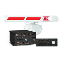
JRC JMR-5410-4X Instruction Manual (126 pages)
Multi Function Display
Brand:
JRC
| Category:
Marine Equipment
| Size: 3.56 MB
Table of Contents
Safety Cautions
4
Emergency Measures
5
Pictorial Indication
12
Precautions Upon Equipment Operation
13
Glossary
21
Table of Contents
27
Section 1 Overview of the Function
29
What Is the Radar Image LAN Distribution Function
29
Features and Restrictions of the Function
30
Configuration
33
Section 2 Common Operations
35
Turning ON/OFF the Radar Image Distribution Function
35
Checking Scanner Information
36
Section 3 Simple ISW (LAN) Function
39
Enabling the Function
39
Failure Countermeasures
42
Screen Structure
43
Operation Restrictions Other than those on the Top Screen
49
Section 4 Target Tracking
53
Features and Restrictions
53
TT Function
55
Setting Target Tracking
58
Track Function
69
Highlighting TT/AIS Symbols
71
Trial Manoeuvring
73
Section 5 Installation Setting and Checking (Supported by Service)
77
Installation Setting Menu
77
Enabling the Function
78
Setting a Network
79
Checking the Network Communication Status
81
Section 6 Failures and After-Sale Services
84
Countermeasures for Failures
84
Troubleshooting
85
After-Sale Services
95
Appendix A Interconnection Diagram for Radar Video LAN Distribution
97
Interconnection Diagram
98
Appendix B Alert List
99
Alarms
100
Warnings
100
Cautions
101
Informations
102
List of Alert Icons
103
Appendix C Menu List and Materials
105
Menu List
105
Software Licence Agreement
119
Font Licence Agreement
120
IPA Font Licence Agreement V1.0
121
Advertisement
JRC JMR-5410-4X Simplified Instruction Manual (40 pages)
MARINE RADAR EQUIPMENT
Brand:
JRC
| Category:
Marine Radar
| Size: 1.38 MB
Table of Contents
Table of Contents
3
Introduction
5
Read before Use
5
Basic Operation
7
Powering on and Starting
7
Finishing and Stopping Operation
8
Adjusting Screen Brightness
9
Adjust the Screen Using the Right Tool Bar
9
Adjust the Screen Using the [MULTI] Dial
9
Changing the Observation Range
10
Adjusting Gain
11
Removing Sea Clutters
12
Removing Rain/Snow Clutters
14
Using the Electronic Bearing Line(EBL) and Variable Range Marker(VRM)
16
Measuring a Range and a Bearing with EBL and VRM
16
Measuring between Arbitrary Two Points
17
Switching the Transmission Pulse Length
18
Switching the Azimuth Mode
19
Switching the Motion Mode
20
Resetting Own Ship to Its Initial Position in [TM] (True Motion Display) Mode
21
Displaying Radar Trail
22
Changing the Trail Length
22
Erasing a Radar Trail
22
Changing the Display Mode of Radar Trails
23
Section 3 Operation of Target Tracking
25
Acquiring a Target
25
Auto Acquisition (Automatic Acquisition) Mode
25
ACQ MANUAL (Manual Acquisition) Mode
26
Using Manual Acquisition and Auto Acquisition Together
26
Displaying the Information of Tracking Targets
27
Erased Tracked Targets
28
AIS Operation
29
Setting up the AIS Display Function
29
Activating an AIS Target
30
Manual Activation
30
Automatic Activation
30
Displaying the AIS Information
31
Deactivating an AIS Target
32
Operation Common to Target Tracking and AIS
33
Setting up Vectors
33
Setting up the Vector Mode
33
Setting up the Vector Length
33
Setting up the Collision Determining Condition
34
Setting up the CPA Limit
34
Setting up the TCPA Limit
34
Other Operations
35
Stopping an Alert
35
Acknowledging an Alert
36
Operation with the Software Keyboard
37
JRC JMR-5410-4X Instruction Manual (40 pages)
Brand:
JRC
| Category:
Marine Radar
| Size: 1.39 MB
Table of Contents
Table of Contents
3
Introduction
5
Read before Use
5
Basic Operation
7
Powering on and Starting
7
Finishing and Stopping Operation
8
Adjusting Screen Brightness
9
Adjust the Screen Using the Right Tool Bar
9
Adjust the Screen Using the [MULTI] Dial
9
Changing the Observation Range
10
Adjusting Gain
11
Removing Sea Clutters
12
Removing Rain/Snow Clutters
14
Using the Electronic Bearing Line(EBL) and Variable Range Marker(VRM)
16
Measuring a Range and a Bearing with EBL and VRM
16
Measuring between Arbitrary Two Points
17
Switching the Transmission Pulse Length
18
Switching the Azimuth Mode
19
Switching the Motion Mode
20
Resetting Own Ship to Its Initial Position in [TM] (True Motion Display) Mode
21
Displaying Radar Trail
22
Changing the Trail Length
22
Erasing a Radar Trail
22
Changing the Display Mode of Radar Trails
23
Section 3 Operation of Target Tracking
25
Acquiring a Target
25
Auto Acquisition (Automatic Acquisition) Mode
25
ACQ MANUAL (Manual Acquisition) Mode
26
Using Manual Acquisition and Auto Acquisition Together
26
Displaying the Information of Tracking Targets
27
Erased Tracked Targets
28
AIS Operation
29
Setting up the AIS Display Function
29
Activating an AIS Target
30
Manual Activation
30
Automatic Activation
30
Displaying the AIS Information
31
Deactivating an AIS Target
32
Operation Common to Target Tracking and AIS
33
Setting up Vectors
33
Setting up the Vector Mode
33
Setting up the Vector Length
33
Setting up the Collision Determining Condition
34
Setting up the CPA Limit
34
Setting up the TCPA Limit
34
Other Operations
35
Stopping an Alert
35
Acknowledging an Alert
36
Operation with the Software Keyboard
37
Advertisement
Related Products
JRC JMR-5410-6XH
JRC JMR-5410-6X
JRC JMR-5425-7X
JRC JMR-5425-6XH
JRC JMR-5472-S
JRC JMR-5430-S
JRC JMR-5482-SH
JRC JMR-5404-X
JRC JMR-5406-X
JRC JMR-5482-S
JRC Categories
Water Filtration Systems
Marine Radar
Marine Equipment
Radio Parts
Receiver
More JRC Manuals
Login
Sign In
OR
Sign in with Facebook
Sign in with Google
Upload manual
Upload from disk
Upload from URL