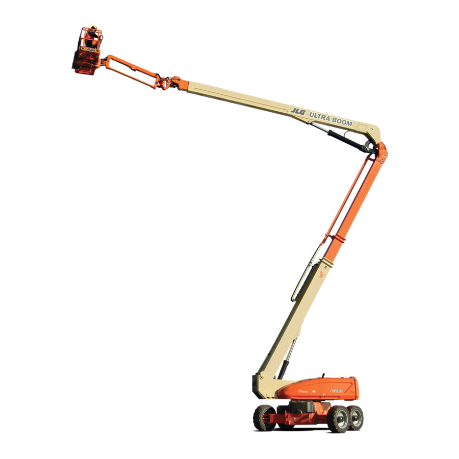
Sign In
Upload
Manuals
Brands
JLG Manuals
Boom Lifts
1250AJP
JLG 1250AJP Manuals
Manuals and User Guides for JLG 1250AJP. We have
4
JLG 1250AJP manuals available for free PDF download: Troubleshooting Manual, Operation And Safety Manual, Operation & Safety Manual, Quick Reference
JLG 1250AJP Troubleshooting Manual (326 pages)
Brand:
JLG
| Category:
Boom Lifts
| Size: 19.35 MB
Table of Contents
Section A. Introduction
3
How to Use this Manual
3
Visual Inspection
4
Reading Fault Codes
4
Connector References
5
Control Module Power
6
Critical Sensors
7
Service Fault Code Cross References
9
Section B. Troubleshooting Safety Precautions
19
General
19
Hydraulic System Safety
19
Troubleshooting Safety
19
Revision Log
20
Table of Contents
21
Section 1. Fault Dictionary and Selected Troubleshooting
35
Air Filter Bypassed
35
Alternator Power Short to Ground
35
Aux Power Open Circuit
35
Aux Power Short to Battery
35
Aux Power Short to Ground
35
Axle Ext Stb or Oc
35
Axle Ext Stg
35
Axle Ret Stb or Oc
35
Axle Ret Stg
36
Backup Blam Communications Active
36
Basket down Override Open Circuit
36
Basket down Override Short to Battery
36
Basket down Override Short to Ground
36
Basket down Short to Battery or Open Circuit
36
Basket down Short to Ground
36
Basket Left Open Circuit
36
Basket Left Short to Battery
36
Basket Left Short to Ground
37
Basket Leveling Crackpoint down Not Calibrated
37
Basket Leveling Crackpoint up Not Calibrated
38
Basket Leveling Override off
39
Basket Leveling Override on
39
Basket Leveling Sensor 1 Short to Battery
39
Basket Leveling Sensor 1 Short to Ground or Open Circuit
39
Basket Leveling Sensor 2 Short to Battery
39
Basket Leveling Sensor 2 Short to Ground or Open Circuit
39
Basket Leveling System Timeout
39
Basket Leveling Tilt Reference 1 out of Range
41
Basket Leveling Tilt Reference 2 out of Range
41
Basket Leveling Tilt Sensor 1 Communications Lost
41
Basket Leveling Tilt Sensor 2 Communications Lost
43
Basket Leveling Tilt Sensor Difference too Great
44
Basket Right Open Circuit
44
Basket Right Short to Battery
44
Basket Right Short to Ground
45
Basket up Override Open Circuit
45
Basket up Override Short to Battery
45
Basket up Override Short to Ground
45
Basket up Short to Battery or Open Circuit
45
Basket up Short to Ground
45
Battery Low
45
Battery too High - System Shut down
45
Battery too Low - System Shut down
45
Blam Backup Communications Link Faulty
46
Blam Backup Communications Lost - Hydraulics Suspended
47
Blam Can Communications Lost
48
Blam High Res A/D Failure
53
Blam Sensor Supply out of Range High
53
Blam Sensor Supply out of Range Low
54
Boom Angle Sensor #1 Communications Fault
54
Boom Angle Sensor #2 Communications Fault
56
Boom Length Sensor #1 out of Range High
57
Boom Length Sensor #1 out of Range Low
58
Boom Length Sensor #2 out of Range High
58
Boom Length Sensor #2 out of Range Low
58
Boom Prevented - Drive Selected
58
Boom Sensors Not Calibrated
58
Can Dongle Attached - Hydraulics Not Restricted
58
Chassis Can Communications Lost
58
Chassis Sensor Supply out of Range High
60
Chassis Sensor Supply out of Range Low
61
Chassis Tilt Sensor Gain out of Range
61
Chassis Tilt Sensor Not Calibrated
62
Chassis Tilt Sensor Not Gain Calibrated
62
Chassis Tilt Sensor out of Range
62
Cold Start Advance Solenoid Open Circuit
62
Cold Start Advance Solenoid Short to Battery
62
Cold Start Advance Solenoid Short to Ground
62
Coolant Temperature Short to Ground
62
Cyl Angle Sensor/Sw Disagreement
62
Cylinder Load Pin Can Communications Lost
63
D/S Joy. Center Tap Bad
64
D/S Joy. out of Range High
64
D/S Joy. out of Range Low
64
Dcap Len Sw Disagreement
64
Disconnect Analyzer and Cycle Ems to Perform Boom Retrieval
67
Drive & Boom Prevented - Platform Overloaded
67
Drive Crackpoints Not Calibrated
67
Drive Locked - Joystick Moved before Footswitch
68
Drive Prevented - above Elevation
68
Drive Prevented - Boom Selected
68
Drive Prevented - Tilted & above Elevation
68
Eeprom Failure - Check All Settings
69
Electric Pump Open Circuit
69
Electric Pump Short to Battery
69
Electric Pump Short to Ground
69
Engine Controller Can Communications Lost
69
Engine Shutdown - Axle Lockout Valve Fault
70
Engine Trouble Code
70
Common Deutz Engine Fault Codes
70
Common Deutz Engine Fault Codes Table
72
Envelope Control Disabled
73
Envelope Encroached - Hydraulics Suspended
73
Everything Ok
73
Excessive Can Bus Communication Errors
73
Footswitch Selected before Start
77
Front Left Wheel Blocked
77
Front Left Wheel Sensor Fault - Check Mounting
78
Front Left Wheel Sensor out of Range High
80
Front Left Wheel Sensor out of Range Low
81
Front Right Wheel Blocked
82
Front Right Wheel Sensor Fault - Check Mounting
83
Front Right Wheel Sensor out of Range High
84
Front Right Wheel Sensor out of Range Low
85
Fsw Faulty
85
Fsw Interlock Tripped
86
Fsw Open
86
Fuel Sensor Short to Battery
87
Fuel Sensor Short to Ground
87
Functions Locked out - Blam Module Software Version Improper
87
Functions Locked out - Chassis Module Software Version Improper
87
Functions Locked out - Platform Module Software Version Improper
87
Gen Set/Welder Open Circuit
87
Gen Set/Welder Short to Battery
88
Gen Set/Welder Short to Ground
88
Generator Motion Cutout Active
88
Ground Alarm Open Circuit
88
Ground Alarm Short to Battery
88
Glow Plug Open Circuit
88
Head Tail Light Open Circuit
89
Ground Module Constant Data Update Required
89
Ground Module Failure: Hwfs Code
89
Ground Module Failure:high Side Driver Cutout Faulty
89
Ground Sensor Ref Voltage out of Range
89
Head Tail Light Short to Battery
89
Head Tail Light Short to Ground
90
High Engine Temp
90
High Resolution A2D Failure-Interrupt Lost
90
High Resolution A2D Failure-Reinit Limit
90
Horn Open Circuit
90
Horn Short to Battery
90
Horn Short to Ground
90
Hour Meter Short to Battery
90
Hour Meter Short to Ground
90
Jib down Open Circuit
91
Invalid Angle Sensor #1 Model
91
Invalid Angle Sensor #2 Model
91
Jib down Short to Battery
91
Jib down Short to Ground
91
Jib Left Open Circuit
91
Keyswitch Faulty
92
Jib Left Short to Battery
92
Jib Left Short to Ground
92
Jib Right Open Circuit
92
Jib Right Short to Battery
92
Jib Right Short to Ground
92
Jib Swing Prevented - in 1000# Mode
92
Jib up Open Circuit
92
Jib up Short to Battery
92
Jib up Short to Ground
92
L/S Joy. Center Tap Bad
93
Left Forward Drive Pump Open Circuit
93
Left Forward Drive Pump Short to Battery
93
Left Forward Drive Pump Short to Ground
93
Left Reverse Drive Pump Open Circuit
93
Left Reverse Drive Pump Short to Battery
93
Left Reverse Drive Pump Short to Ground
93
Length Sensor Ref Voltage High
94
Length Sensor Ref Voltage Low
94
Lift up & Tele out Prevented - Platform Overloaded
94
Lift/Swing Locked - Joystick Moved before Footswitch
95
Load Pin Force too Low over Main Angle Change
95
Load Pin Force too Low over Main Length Transition
95
Load Pin Force too Low over Tower Angle Change
95
Load Pin Force Values Not Changing
95
Load Pin Horizontal Force out of Range
95
Load Pin Not Calibrated
95
Load Pin Sensor Fault
96
Load Pin Vertical Force out of Range
96
Load Pin/Tower Lift Cylinder Angle Disagreement
96
Load Sensor Not Calibrated
96
Load Sensor Reading under Weight
96
Low Oil Pressure
96
Lt Fnt Steer Lt Stb or Oc
97
Lt Fnt Steer Lt Stg
98
Lt Fnt Steer Rt Stb or Oc
98
Lt Fnt Steer Rt Stg
99
Lt Rear Steer Lt Stb or Oc
99
Lt Rear Steer Lt Stg
99
Lt Rear Steer Rt Stb or Oc
99
Lt Rear Steer Rt Stg
100
Main Angl1 Can Communications Lost
100
Main Angl1 Invalid Angle
101
Main Angl2 Can Communications Lost
102
Main Angl2 Invalid Angle
103
Main Angle Movement Without CMD
104
Main Angle Sensor Disagreement
104
Main Angle Sensor Not Detecting Angle Change
105
Main Boom Trn Angle Sw/Sensor Disagreement
108
Main Dump Open Circuit
109
Main Dump Short to Battery
109
Main Dump Short to Ground
109
Main Envelope Encroached - Hydraulics Suspended
109
Main in Open Circuit
109
Main in Short to Battery
109
Main in Short to Ground
109
Main Lift Apu Open Circuit
109
Main Lift Apu Short to Battery
110
Main Lift Apu Short to Ground
110
Main Lift Enable Open Circuit
110
Main Lift Enable Short to Battery
110
Main Lift Enable Short to Ground
110
Main Lift Pilot Pressure Failure
110
Main Lift Pilot Pressure Switch Failure
110
Main Lift Pvg Valve Command Improper
110
Main Lift Pvg Valve Communications
111
Main Lift Pvg Valve High Voltage
111
Main Lift Pvg Valve Internal Fault
112
Main Lift Pvg Valve Location Improper
112
Main Lift Pvg Valve Low Voltage
112
Main Lift Pvg Valve Obstructed
113
Main Lift Pvg Valve Parameters Incorrect
114
Main Lift Pvg Valve Sent Unrecognized Fault
114
Main Lift Pvg Valve Setup Fault
114
Main Lift Pvg Valve Stuck Extended
114
Main Lift Pvg Valve Stuck Neutral
114
Main Lift Pvg Valve Stuck Retracted
114
Main Lift Pvg Valve Timeout
115
Main Lift Pvg Valve Wiring Incorrect
115
Main out Open Circuit
115
Main out Short to Battery
115
Main out Short to Ground
115
Main Tele Flow Control Open Circuit
115
Main Tele Flow Control Short to Battery
116
Main Tele Flow Control Short to Ground
116
Main Trn Angle Sw Failed
116
Main Trn Len Sw Disagreement
118
Model Changed - Hydraulics Suspended - Cycle Ems
120
Moment Control Disabled
120
New Load Pin Detected Fault
121
New Main Angl1 Sensor Detected
121
New Main Angl2 Sensor Detected
121
No Alternator Output
121
No Main Lift Pilot Pressure
121
Oil Pressure Short to Battery
121
Oil Pressure Short to Ground
122
Parking Brake Open Circuit
122
Parking Brake Short to Battery
122
Parking Brake Short to Ground
122
Platform Can Communications Lost
122
Platform Control Valve Open Circuit
123
Platform Control Valve Short to Battery
123
Platform Control Valve Short to Ground
123
Platform Module Failure: Hwfs Code 1
123
Platform Module Software Update Required
123
Platform Sensor Ref Voltage out of Range
124
Pump Switches Faulty - Check Diagnostics/Boom
125
Pump Switches Locked - Selected before Aux Power
125
Pump Switches Locked - Selected before Footswitch
125
Pump Switches Locked - Selected before Start Switch
125
Pvg Valve Enable Open Circuit
125
Pvg Valve Enable Short to Battery
126
Pvg Valve Enable Short to Ground
126
Rear Left Wheel Blocked
126
Rear Left Wheel Sensor Fault - Check Mounting
127
Rear Left Wheel Sensor out of Range High
128
Rear Left Wheel Sensor out of Range Low
129
Rear Right Wheel Blocked
130
Rear Right Wheel Sensor Fault - Check Mounting
131
Rear Right Wheel Sensor out of Range High
132
Rear Right Wheel Sensor out of Range Low
133
Restricted to Transport - Axle Lockout Valve Stb or Oc
134
Restricted to Transport - Osc Axle Press Sw Disagreement
135
Restricted to Transport - Parking Brake Stb
137
Right Forward Drive Pump Open Circuit
137
Right Forward Drive Pump Short to Battery
137
Right Forward Drive Pump Short to Ground
138
Right Reverse Drive Pump Open Circuit
138
Right Reverse Drive Pump Short to Battery
138
Right Reverse Drive Pump Short to Ground
138
Rt Fnt Steer Lt Stb or Oc
138
Rt Fnt Steer Lt Stg
138
Rt Fnt Steer Rt Stb or Oc
138
Rt Fnt Steer Rt Stg
138
Rt Rear Steer Lt Stb or Oc
138
Rt Rear Steer Lt Stg
138
Rt Rear Steer Rt Stb or Oc
139
Rt Rear Steer Rt Stg
139
Running at Creep - Creep Switch Open
139
Running at Creep - Platform Overloaded
140
Running at Creep - Tilted and above Elevation
140
Running at Cutback - out of Transport Position
141
Speed Input Lost
141
Speed Sensor Reading Invalid Speed
141
Start Solenoid Open Circuit
141
Start Solenoid Short to Battery
142
Start Solenoid Short to Ground
142
Start Switch Locked - Selected before Keyswitch
142
Steer Locked - Selected before Footswitch
142
Steer Sensors Not Calibrated
142
Steer Switches Faulty
142
Swing Left Open Circuit
142
Swing Left Short to Battery
142
Swing Right Open Circuit
142
Swing Right Short to Battery
143
Throttle Actuator Failure
143
Throttle Actuator Open Circuit
143
Throttle Actuator Short to Battery
143
Throttle Actuator Short to Ground
143
Tower Angle Sensor Disagreement
143
Tower Envelope Encroached - Hydraulics Suspended
144
Tower Length Sensor Disagreement
144
Tower Length Switch/Sensor Disagreement
145
Tower Lift Apu Valve Open Circuit
147
Tower Lift Apu Valve Short to Battery
147
Tower Lift Apu Valve Short to Ground
148
Tower Lift Apu Valve Stuck Open
148
Tower Lift Enable Open Circuit
148
Tower Lift Enable Short to Battery
148
Tower Lift Enable Short to Ground
148
Tower Lift Enable Stuck Open
148
Tower Lift Pvg Valve Command Improper
148
Tower Lift Pvg Valve Communications
149
Tower Lift Pvg Valve High Voltage
149
Tower Lift Pvg Valve Internal Fault
150
Tower Lift Pvg Valve Location Improper
150
Tower Lift Pvg Valve Low Voltage
150
Tower Lift Pvg Valve Obstructed
151
Tower Lift Pvg Valve Parameters Incorrect
152
Tower Lift Pvg Valve Send Unrecognized Fault
152
Tower Lift Pvg Valve Setup Fault
152
Tower Lift Pvg Valve Stuck Extended
152
Tower Lift Pvg Valve Stuck Neutral
152
Tower Lift Pvg Valve Stuck Retracted
152
Tower Lift Pvg Valve Timeout
153
Tower Lift Pvg Valve Wiring Incorrect
153
Tower Tele Apu Valve Stuck Open
153
Tower Tele Enable Open Circuit
153
Tower Tele Enable Short to Battery
153
Tower Tele Enable Short to Ground
153
Tower Tele Enable Stuck Open
154
Tower Telescope Apu Open Circuit
154
Tower Telescope Apu Short to Battery
154
Tower Telescope Apu Short to Ground
154
Tower Telescope Pvg Valve Command Improper
154
Tower Telescope Pvg Valve Communications
154
Tower Telescope Pvg Valve High Voltage
155
Tower Telescope Pvg Valve Internal Fault
155
Tower Telescope Pvg Valve Location Improper
156
Tower Telescope Pvg Valve Low Voltage
156
Tower Telescope Pvg Valve Obstructed
157
Tower Telescope Pvg Valve Parameters Incorrect
157
Tower Telescope Pvg Valve Sent Unrecognized Fault
158
Tower Telescope Pvg Valve Setup Fault
158
Tower Telescope Pvg Valve Stuck Extended
158
Tower Telescope Pvg Valve Stuck Neutral
158
Tower Telescope Pvg Valve Stuck Retracted
158
Tower Telescope Pvg Valve Timeout
158
Tower Telescope Pvg Valve Wiring Incorrect
159
Trn Dual Cap Bad Transition
159
Trn Dual Cap Switches Bad
160
Two Speed Open Circuit
160
Two Speed Short to Battery
160
Two Speed Short to Ground
160
Twr Angl1 Invalid Angle
161
Twr Angl2 Invalid Angle
161
Twr Cyl Angle Movement Without CMD
162
Twr Cyl Angle Not Detecting Angle Change
162
Twr Cyl Angle Sensor out of Range High
164
Twr Cyl Angle Sensor out of Range Low
164
Twr Length Movement Without CMD
165
Twr Length Sensor Not Detecting Length Change
166
Twr Length Sensor One Value out of Range High
167
Twr Length Sensor One Value out of Range Low
168
Twr Length Sensor Two Value out of Range High
169
Twr Length Sensor Two Value out of Range Low
170
Twr Trn Sw Disagreement
171
Waiting for Fsw to be Open
172
Wrong Engine Selected - Ecm Present
172
Wrong Main Lift Response
173
Wrong Main Tele Response
173
Wrong Twr Lift Response
173
Wrong Twr Tele Response
174
Common Stb or Oc Procedure
174
Common Stg Procedure
175
Limit Switch States
177
Main Boom Dual Capacity Zones
178
Switch States / Boom Length Regions
179
Platform Area Solenoids
182
Main Valve Area Solenoids
188
Chassis Area Solenoids
192
Connector Index
209
Connector Index
214
X086 (J1) BLAM Module Pinout
215
X087 (J2) BLAM Module Pinout
215
X088 (J3) BLAM Module Pinout
215
Blam Module Connector Pinouts
215
X089 (J4) BLAM Module Pinout
216
X090 (J5) BLAM Module Pinout
216
X229 (J1) Chassis Module Pinout
217
X230 (J2) Chassis Module Pinout
217
X231 (J3) Chassis Module Pinout
217
Chassis Module Connector Pinouts
217
X232 (J4) Chassis Module Pinout
218
X233 (J5) Chassis Module Pinout
218
Ground Module Connector Pinouts
219
Platform Module Connector Pinouts
223
Connector Loading Diagrams
227
Working with Amp Connectors
239
Working with Deutsch Connectors
244
Ground Analyzer Connection Point
261
Platform Analyzer Connection Point
261
Using the Analyzer
261
Analyzer Flow Chart
263
Analyzer Flow Chart - Personalities (Software Version 6.X to Present)
264
Analyzer Flow Chart - Machine Setup (Software Version 6.X to Present)
265
Analyzer Flow Chart - Calibrations (Software Version 6.X to Present)
266
Machine Setup
271
System Test
282
System Test Flow Chart - Platform Tests
284
System Test Flow Chart - Ground Station Tests
286
Calibrating Steer
290
Calibrating Drive
292
Calibrating Boom Valves
296
Electronic Platform Leveling
299
Calibrating Platform Level
302
Calibrating Tilt Sensor
307
Boom Sensor Calibration
309
Voltage Measurement (DC)
320
Resistance Measurement
320
Current Measurement (DC)
321
Continuity Measurement over Long Distances
321
Example Circuit Schematic
322
Example Continuity Test Setup
323
Advertisement
JLG 1250AJP Operation And Safety Manual (173 pages)
Brand:
JLG
| Category:
Boom Lifts
| Size: 12.25 MB
Table of Contents
Table of Contents
8
Section 1 - Safety Precautions
16
General
16
Pre-Operation
16
Operator Training and Knowledge
16
Workplace Inspection
17
Machine Inspection
18
Operation
18
General
18
Trip and Fall Hazards
19
Electrocution Hazards
20
Tipping Hazards
22
Crushing and Collision Hazards
25
Towing, Lifting, and Hauling
26
Maintenance
26
Maintenance Hazards
26
Battery Hazards
28
Section 2. User Responsibilities, Machine Preparation, and Inspection
31
2.1 Personnel Training
31
Operator Training
31
Training Supervision
31
Operator Responsibility
31
2.2 Preparation, Inspection, and Maintenance
32
Pre-Start Inspection
35
Daily Walk-Around Inspection
36
Function Check
38
Skyguard Function Test
39
Oscillating Axle Lockout Test (if Equipped)
40
Section 3 - Machine Controls and Indicators
41
General
41
Controls and Indicators
41
Ground Control Station
43
Ground Control Indicator Panel
48
Platform Station
50
Platform Control Indicator Panel
56
Section 4 - Machine Operation
63
Description
63
Hydraulic System Warm up
64
Boom Operating Characteristics and Limitations
64
Capacities
64
Envelope Control System
65
Tower Path Control System
66
Automatic Main Boom Control System
67
Slow down System
67
Controlled Angle
68
Swing Speed Proportioning
68
Stability
68
Auxiliary Power Operation
72
Capacity Select
72
Engine Operation
74
Starting Procedure
74
Shutdown Procedure
75
Air Shutoff Valve (ASOV) (if Equipped)
75
Fuel Reserve / Shut-Off System
76
Traveling (Driving)
78
Traveling Forward and Reverse
80
Traveling on a Grade
80
Steering
81
Extending the Axles
81
4.10 Platform
81
Platform Level Adjustment
81
Platform Rotation
81
4.11 Boom
81
Swinging the Boom
82
Raising and Lowering the Main Boom
82
Telescoping the Main Boom
82
Tower Lift
82
Swinging the Jib
83
4.12 Function Speed Control
83
Machine Safety System Override (Msso)
83
4.14 Skyguard Operation
84
Skyguard
84
Skyguard - Skyline
84
Skyguard - Skyeye
85
Skyguard Function Table
85
4.15 Emergency Towing
86
4.16 Shut down and Park
87
4.17 Lifting and Tie down
87
Lifting
87
Tie down
88
4.18 Stowing the Jib for Transport
88
Section 5 - Emergency Procedures
111
General
111
Incident Notification
111
Emergency Operation
111
Operator Unable to Control Machine
111
Platform or Boom Caught Overhead or Boom Movement Prevented by Boom Control System
112
Emergency Towing Procedures
112
Machine Safety System Override (Msso)(Ce Only)
113
Section 6 - Accessories
116
Fall Arrest Platform
118
Safety Precautions
118
Pipe Racks
118
Capacity Specifications (Australia Only)
119
Safety Precautions
119
Preparation and Inspection
119
Operation
119
Skycutter
120
Safety Precautions
120
Accessory Ratings
121
Generator Output
121
Preparation and Inspection
121
Operation
121
Skyglazier
122
Capacity Specifications
122
Safety Precautions
123
Preparation and Inspection
123
Operation
123
Skypower
124
Generator Output
124
Accessory Ratings
124
Safety Precautions
125
Preparation and Inspection
125
Operation
125
Skywelder
125
Accessory Ratings
126
Generator Output
126
Welding Accessories
126
Safety Precautions
127
Preparation and Inspection
127
Operation
127
Soft Touch
128
Bolt-On External Fall Arrest
128
Inspection before Use
129
Section 7 - General Specifications & Operator Maintenance
132
Introduction
132
Operating Specifications and Performance
132
Data
132
Dimensional Data
134
Chassis
134
Capacities
135
Tires
135
Engine Data - Deutz 2011 Prior to S/N 0300127698
136
Present
136
Engine Data - Caterpillar
137
Hydraulic Oil
138
Operator Maintenance
149
Tires & Wheels
165
Tire Inflation
165
Tire Damage
165
Tire Replacement
166
Wheel and Tire Replacement
166
Wheel Installation
166
Supplemental Information
168
JLG 1250AJP Operation & Safety Manual (160 pages)
Brand:
JLG
| Category:
Boom Lifts
| Size: 22.37 MB
Table of Contents
Foreword
3
Revision Log
7
Table of Contents
9
Safety Precautions
13
General
13
Pre-Operation
13
Operation
15
Towing, Lifting, and Hauling
21
Maintenance
21
User Responsibilities, Machine Preparation, and Inspection
25
Personnel Training
25
Preparation, Inspection, and Maintenance
26
1250AJ Machine Components
28
Pre-Start Inspection
29
1250AJP Walk-Around Inspection
30
Function Check
32
Skyguard® Function Test
33
Oscillating Axle Lockout Test (if Equipped)
34
Machine Controls and Indicators
35
General
35
Controls and Indicators
36
Ground Control Station
37
Ground Control Indicator Panel
43
Platform Control Station
46
Platform Control Indicator Panel
51
Machine Operation
55
General
55
Hydraulic System Warm up
55
Operating Characteristics and Limitations
55
Stability
60
Engine Operation
63
Air Shutoff Valve (ASOV) (if Equipped)
66
Fuel Shutoff System (Reserve)
67
Diesel Particulate Filter (if Equipped)
67
Auxiliary Power Operation
68
Capacity Zones (Dual Capacity with a Capacity Select Switch)
69
Traveling (Driving)
69
Traveling (Grade/Side Slope)
71
Steering
72
Extending the Axles
72
Platform
73
Boom
73
Function Speed Control
76
USB Charging Port
76
Machine Safety System Override (MSSO) (if Equipped)
77
Skyguard Operation
77
Emergency Towing
80
Shut down and Park
81
Lifting and Tie down
81
Stowing the Jib for Transport
82
Lifting Chart
83
Safety Decals
83
Emergency Procedures
91
General
91
Incident Notification
91
Emergency Operation
92
Emergency Towing Procedures
92
Machine Safety System Override (MSSO) (if Equipped)
93
Accessories
95
Available Accessories and Relationship Table
95
Bolt-On External Fall Arrest
99
Cable Ladder Carrier
101
Fabric Mesh to MID or Top Rail
102
Fall Arrest Platform
102
Nite Bright
103
Pipe Racks
104
Platform Mesh to MID or Top Rail
106
Platform Top Rail Extension
107
Platform Work Lights
108
Platform Work Surface
109
Skycutter
110
Skyglazier
113
Skypower® 7.5 Kw and Generator 4 Kw
115
Skysense
117
Skysense® Platform Bumper Padding
122
Skywelder
123
Soft Touch
126
General Specifications and Operator Maintenance
127
General
127
Operating Specifications and Performance Data
127
Hydraulic Oil Operation Chart
133
Engine Oil Operating Temperature Specifications
134
Operator Maintenance and Lubrication Diagrams
135
Operator Maintenance
136
Tires and Wheels
152
Supplemental Information Only Applicable to CE/UKCA Machines
154
EC Declaration of Conformity
155
UKCA Declaration of Conformity
156
Advertisement
JLG 1250AJP Quick Reference (2 pages)
Brand:
JLG
| Category:
Lifting Systems
| Size: 0.17 MB
Advertisement
Related Products
JLG 1255
JLG 120SXJ
JLG SKYTRAK 12054
JLG 1930ES
JLG 100HX
JLG 110HX
JLG 1030P
JLG 1500SJ
JLG 110SX
JLG 1055
JLG Categories
Boom Lifts
Lifting Systems
Scissor Lifts
Construction Equipment
Forklifts
More JLG Manuals
Login
Sign In
OR
Sign in with Facebook
Sign in with Google
Upload manual
Upload from disk
Upload from URL