Sign In
Upload
Manuals
Brands
Genie Manuals
Boom Lifts
Z-45 XC
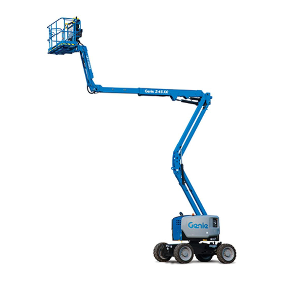
Genie Z-45 XC Manuals
Manuals and User Guides for Genie Z-45 XC. We have
4
Genie Z-45 XC manuals available for free PDF download: Service Manual, Maintenance Manual, Operating Manual, Operator's Manual Supplement
Genie Z-45 XC Service Manual (440 pages)
Brand:
Genie
| Category:
Boom Lifts
| Size: 7.33 MB
Table of Contents
Table of Contents
5
Specifications
19
Machine Specifications
19
Performance Specifications
20
Hydraulic Specifications
22
Ford LRG-425 EFI Engine Specifications
23
Deutz F3L 1011F Engine Specifications
25
Hydraulic Hose and Fitting Torque Specifications
27
Theory of Operation
29
Power Source
29
Hydraulic System
29
Electrical System
29
Limit Switches
30
Machine Controls
30
Maintenance Inspection Report
33
Inspect the Operator's and Safety Manuals
35
Inspect the Decals and Placards
35
Inspect for Damage and Loose or Missing Parts
36
Check the Engine Oil Level
37
Check the Engine Coolant Level - Liquid Cooled Models
38
Check for Fuel Leaks
38
Check the Hydraulic Oil Level
39
Check for Hydraulic Leaks
40
Check the Tire Pressure
40
Test the Oscillate Axle (if Equipped)
41
Test the Platform and Ground Controls
41
Test the Auxiliary Power Operation
42
Test the Tilt Sensor
43
Test the Limit Switches
44
Check the Engine Belt - Perkins Diesel Models
48
Replace the Fuel Filters - Ford Models
50
Inspect the Radiator - Perkins Models
51
Perform 30 Day Service
52
Inspect the Fuel Filter/Water Separator - Diesel Models
54
Check and Adjust the Engine RPM - Perkins Diesel Models
56
Check the Engine Belt - Ford Models
58
Check the Battery
59
Inspect the Electrical Wiring
59
Check the Radiator - Ford Models
60
Check the Exhaust System
61
Check the Hydraulic Return Filter Condition Indicator
62
Check the Oil Cooler and Cooling Fins - Deutz Diesel Models
62
Inspect the Tires and Wheels (Including Lug Nut Torque)
63
Confirm the Proper Brake Configuration
64
Check the Oil Level in the Drive Hubs
64
Test the Key Switch
67
Test the Emergency Stop Buttons
67
Test the Ground Control Override
68
Check the Directional Valve Linkage
68
Test the Platform Self-Leveling
69
Test the Horn
70
Test the Foot Switch
70
Test the Engine Idle Select
71
Test the Fuel Select Operation - Ford Models
72
Test the Drive Enable System
73
Test the Drive Brakes
74
Test the Drive Speed - Stowed Position
75
Test the Drive Speed - Raised or Extended Position
76
Test the Alarm Package - Optional Equipment
77
Replace the Hydraulic Tank Return Filter
78
Replace the Fuel Filter/Water Separator Element - Perkins Diesel Models
79
Replace the Fuel Filter Element - Perkins Diesel Models
81
Replace the Spark Plugs - Ford Models
82
Replace the Engine Air Filter Element
83
Check the Engine Belt- Deutz Diesel Models
85
Replace the Engine Oil and Filter - Deutz Diesel Models
86
Check the Engine Valve Clearances - Deutz Diesel Models
87
Change or Recondition the Engine Coolant - Liquid Cooled Models
88
Check the Engine Valve Clearances - Perkins Diesel Models
89
Replace the PCV Valve - Ford Models
90
Check the Boom Wear Pads
91
Check the Turntable Rotation Bearing Bolts
92
Check the Free-Wheel Configuration
93
Grease the Turntable Rotation Bearing and Rotate Gear
95
Replace the Drive Hub Oil
96
Replace the Drive Loop Hydraulic Filter
97
Check and Adjust the Air/Lpg Mixture - Ford Models
98
Replace the Diesel Fuel Filter/Water Separator - Deutz Diesel Models
99
Test or Replace the Hydraulic Oil
100
Change or Recondition the Engine Coolant - Ford Models
102
Change the Fuel Hoses
104
Check the Toothed Belt - Deutz Diesel Models
107
Check the Engine Valve Clearance - Ford Models
107
Grease the Steer Axle Wheel Bearings, 2WD Models
108
Troubleshooting Flow Charts
111
Fault Codes
113
Engine will Not Crank over
116
Engine Cranks over but will Not Start - Ford Models
118
Engine Runs While Cranking then dies
120
Engine Cranks over but will Not Start - Diesel Models
121
Engine will Not Start on LPG, but will Start on Gasoline - Ford Models
124
Engine will Not Start on Gasoline, but will Start on LPG - Ford Models
126
Engine High Idle Inoperative - Ford Models
127
Engine Low Idle Inoperative - Ford Models
128
Engine High Idle Inoperative - Diesel Models
129
Engine Low Idle Inoperative - Diesel Models
131
All Functions Inoperative, Engine Starts and Runs
132
All Lift and Steer Functions Inoperative, Drive Functions Operational
133
Ground Controls Inoperative, Platform Controls Operate Normally
134
Platform Controls Inoperative, Ground Controls Operate Normally
135
Primary Boom up Function Inoperative
136
Primary Boom down Function Inoperative (before Serial Number 13099)
139
Primary Boom down Function Inoperative (after Serial Number 13098)
142
Secondary Boom up Function Inoperative
145
Secondary Boom down Function Inoperative
148
Primary Boom Extend Function Inoperative
151
Primary Boom Retract Function Inoperative
153
Turntable Rotate Left Function Inoperative
155
Turntable Rotate Right Function Inoperative
159
All Platform Leveling Functions Inoperative
163
Platform Level up Function Inoperative
164
Platform Level down Function Inoperative
166
Platform Rotate Left Function Inoperative
168
Platform Rotate Right Function Inoperative
171
Jib Boom up Function Inoperative, Z-45/25J Models
174
Jib Boom down Function Inoperative, Z-45/25J Models
176
Steer Left Function Inoperative
178
Steer Right Function Inoperative
179
Oscillate Function Inoperative
180
All Drive Functions Inoperative, All Other Functions Operate Normally
181
Drive Forward or Reverse Function Inoperative
184
Traction Function Inoperative
185
Machine will Not Drive at Full Speed
186
Machine Drives at Full Speed with Platform Raised or Extended
187
Drive Enable System Is Malfunctioning
188
Auxiliary Functions Inoperative
189
Electrical Components
192
Electrical Symbols Legend
194
Abbreviation Legend
195
Electrical Schematic, Z-45/25 Ford Models (before Serial Number 13099)
202
Ground Control Box Wiring Diagram-Z-45/25 Ford Models (before Serial Number 13099)
205
Platform Control Box Wiring Diagram-Z-45/25 Ford Models (before Serial Number 13099)
208
Electrical Schematic, Z-45/25 Ford Models (from Serial Number 13098 to 16303)
210
Ground Control Box Wiring Diagram, Z-45/25 Ford Models
213
Platform Control Box Wiring Diagram, Z-45/25 Ford Models
216
Electrical Schematic, Z-45/25J Ford Models (before Serial Number 13099)
218
Ground Control Box Wiring Diagram-Z-45/25J Ford Models (before Serial Number 13099)
221
Platform Control Box Wiring Diagram-Z-45/25J Ford Models (before Serial Number 13099)
223
Electrical Schematic, Z-45/25J Ford Models (from Serial Number 13098 to 16303)
226
Ground Control Box Wiring Diagram, Z-45/25J Ford Models
229
Platform Control Box Wiring Diagram, Z-45/25J Ford Models
232
Electrical Schematic, Z-45/25 Ford Models (after Serial Number 16303)
234
(After Serial Number 16303)
235
Ground Control Box Wiring Diagram-Z-45/25 Ford Models (after Serial Number 16303)
237
Platform Control Box Wiring Diagram-Z-45/25 Ford Models (after Serial Number 16303)
240
Electrical Schematic, Z-45/25J Ford Models (after Serial Number 16303)
242
(After Serial Number 16303)
243
Ground Control Box Wiring Diagram-Z-45/25J Ford Models (after Serial Number 16303)
245
Platform Control Box Wiring Diagram-Z-45/25J Ford Models
248
Electrical Schematic, Z-45/25 Deutz Models (before Serial Number 13099)
250
Ground Control Box Wiring Diagram-Z-45/25 Deutz Models (before Serial Number 13099)
253
Platform Control Box Wiring Diagram-Z-45/25 Deutz Models (before Serial Number 13099)
256
Electrical Schematic, Z-45/25 Deutz Models (from Serial Number 13098 to 16303)
258
Ground Control Box Wiring Diagram, Z-45/25 Deutz Models
261
Platform Control Box Wiring Diagram, Z-45/25 Deutz Models
264
Electrical Schematic, Z-45/25J Deutz Models (before Serial Number 13099)
266
Ground Control Box Wiring Diagram-Z-45/25J Deutz Models (before Serial Number 13099)
269
Platform Control Box Wiring Diagram-Z-45/25J Deutz Models (before Serial Number 13099)
272
Electrical Schematic, Z-45/25J Deutz Models (from Serial Number 13098 to 16303)
274
Ground Control Box Wiring Diagram, Z-45/25J Deutz Models
277
Platform Control Box Wiring Diagram, Z-45/25J Deutz Models
280
Platform Control Box Wiring Diagram - Lift Drive Select Option
281
Platform Control Box Wiring Diagram - Lift/Drive Select Option
281
Platform Control Box Wiring Diagram- Lift/Drive Select Option
282
Electrical Schematic, Z-45/25 Deutz Models (after Serial Number 16303)
284
Ground Control Box Wiring Diagram-Z-45/25 Deutz Models (after Serial Number 16303)
287
Platform Control Box Wiring Diagram-Z-45/25 Deutz Models (after Serial Number 16303)
290
Z-45/25 Deutz Models (after Serial Number 16303)
290
Electrical Schematic, Z-45/25J Deutz Models (after Serial Number 16303)
294
Ground Control Box Wiring Diagram-Z-45/25J Deutz Models (after Serial Number 16303)
297
Platform Control Box Wiring Diagram- Lift/Drive Selectoption, Z-45/25J Deutz Models (after Serial Number 16303)
301
Electrical Schematic, Z-45/25 Perkins Models (before Serial Number 16304)
304
Ground Control Box Wiring Diagram, Z-45/25 Perkins Models (before Serial Number 16304)
307
Platform Control Box Wiring Diagram-Z-45/25 Perkins Models (before Serial Number 16304)
310
Electrical Schematic, Z-45/25J Perkins Models (before Serial Number 16304)
312
Ground Control Box Wiring Diagram-Z-45/25J Perkins Models (before Serial Number 16304)
315
Platform Control Box Wiring Diagram-Z-45/25J Perkins Models (before Serial Number 16304)
318
Platform Control Box Wiring Diagram- Lift/Drive Selectoption
319
Z-45/25J Perkins Models (before Serial Number 16304)
319
Electrical Schematic, Z-45/25 Perkins Models (after Serial Number 16303)
322
Ground Control Box Wiring Diagram-Z-45/25 Perkins Models (after Serial Number 16303)
325
Platform Control Box Wiring Diagram-Z-45/25 Perkins Models (after Serial Number 16303)
328
Electrical Schematic, Z-45/25J Perkins Models (after Serial Number 16303)
332
Ground Control Box Wiring Diagram-Z-45/25J Perkins Models (after Serial Number 16303)
335
Platform Control Box Wiring Diagram-Z-45/25J Perkins Models (after Serial Number 16303)
338
Z-45/25J Perkins Models (after Serial Number 16303)
338
Platform Control Box Wiring Diagram- Load Sensor Option, All Models
341
Hydraulic Symbols Legend
343
2WD Hydraulic Schematic
345
4WD Hydraulic Schematic
347
Repair Procedures
349
Platform Controls
350
Joystick Controllers
350
Horsepower Limiter Board
356
Foot Switch
358
Toggle Switches
359
Platform Components
361
Platform
361
Platform Leveling Slave Cylinder
362
Platform Rotator
363
Jib Boom Components, Z-45/25J Models
366
Jib Boom, Z-45/25J Models
366
Jib Boom Lift Cylinder, Z-45/25J Models
367
Jib Boom / Platform Rotate Manifold Components, Z-45/25J Models
369
Primary Boom Components
370
Plastic Cable Track
370
Primary Boom
375
Primary Boom Lift Cylinder
378
Primary Boom Extension Cylinder
379
Platform Leveling Master Cylinder
380
Secondary Boom Components
382
Secondary Boom
382
Secondary Boom Lift Cylinders
387
Turntable Covers
388
Deutz Engine F3L 1011F
389
RPM Adjustment
389
Flex Plate
389
Perkins 104-22 Engine
391
RPM Adjustment
391
Flex Plate
391
Coolant Temperature and Oil Pressure Gauages
392
Ford LRG-425 EFI Engine
393
Timing Adjustment
393
RPM Adjustment
393
Flex Plate
393
Ground Controls
396
Control Relays
396
Wago Components
397
Engine Fault Codes - Ford Models
398
Hydraulic Pumps
400
Lift/Steer Pump
400
Drive Pump
401
Manifolds
404
Function Manifold Components
404
Valve Adjustments - Function Manifold
410
Turntable Rotation Manifold Components
412
Directional Valve Manifold Components
413
2WD Drive Manifold Components
416
Valve Adjustments, 2WD Drive Manifold
418
4WD Drive Manifold Components
420
Valve Adjustments, 4WD Drive Manifold
424
Fuel and Hydraulic Tanks
425
Fuel Tank
425
Hydraulic Tank
425
Turntable Rotation Components
428
Rotation Hydraulic Motor
428
2WD Steering Axle Components
430
Yoke and Hub
430
Steering Cylinders
432
Tie Rod
433
4WD Steering Axle Components
434
Yoke and Hub
434
Oscillating Axle Components
437
Oscillating Axle Lock-Out Cylinders
437
Non-Steering Axle Components
438
Drive Motor
438
Drive Hub
439
Advertisement
Genie Z-45 XC Maintenance Manual (178 pages)
Brand:
Genie
| Category:
Boom Lifts
| Size: 8.21 MB
Table of Contents
Table of Contents
9
Maintenance Procedures
42
Introduction
42
Maintenance Schedule
44
Pre-Delivery Preparation Report
45
Scheduled - Quarterly April 2018 Maintenance Inspection Report - Booms
46
Scheduled Maintenance Inspection Report - Quarterly or Frequent
46
Scheduled Maintenance Inspection Report - Annual
47
Programmed Maintenance Inspection Report - Booms
48
Commissioning Procedures
49
Perform 50 Hour Service
49
Perform Engine Maintenance - 50 Hours
49
Perform 150 Hour Service
50
Check for Open Bulletins and Owner Registration
51
Quarterly Maintenance Procedures
51
Battery Inspection
52
Inspect the Electrical Wiring
54
Inspect the Electrical Contactor - DC / Bi-Energy Models
55
Check the Exhaust System
56
Inspect the Tires, Wheels and Lug Nut Torque
56
Check the Generator Belts and Pulleys, Bi-Energy Models
57
Check the Oscillate Directional Valve Linkage (if Equipped)
58
Visual Inspection of the Hydraulic Oil
59
Inspect the Hydraulic Filters
60
Check and Adjust the Engine RPM
61
Test the Ground Control Override
66
Test the Alarm Package (if Equipped
67
Test the Alarm Package (if Equipped)
67
Test the Emergency Power System
68
Test the Engine Idle Select - Engine Models
68
Test the Engine Idle Select Operation
68
Test the Fuel Select Operation - Gasoline/Lpg Models
70
Inspect the Calibration Decal - ALC1000 Models
71
Test the Recovery Mode System - ALC-1000 Models
72
Test the Recovery System - ALC-1000 Models
72
Test the Platform Self-Leveling
73
Confirm the Proper Brake Configuration
74
Test the Drive Brakes
74
Test the Drive Speed - Raised or Extended Position
75
Test the Drive Speed - Stowed Position
75
Test the Drive Speed - Raised and Extended Position
76
Test the Drive Speed - Raised and Extended, ALC1000 Models
76
Test the Turntable Level Sensor
78
XC, SX-125 XC, SX-135 XC, SX-150 and SX-180
78
Test the Secondary Boom Angle Sensor - Z-135/70 and ZX-135/70
80
Test the Turntable Level Sensor
81
Test the Primary Boom Angle Sensor - Z-135/70 and ZX-135/70
82
Test the Secondary Boom Angle Sensor
82
Test the Primary Boom Angle Sensor
85
XC, SX-125 XC, SX-135 XC, SX-150 and SX-180
85
Test the Safety Envelope Limit Switches
90
XC, SX-125 XC, SX-135 XC, SX-150 and SX-180
90
Test the Primary Boom Angle Sensor
94
Test the Primary Boom Angle Sensor - Z-80/60
94
Test the Safety Envelope and Circuits
95
Test the Safety Envelope and Circuits - Z-80/60
95
Check the Safety Envelope Limit Switches and Angle
97
Check the Safety Envelope Limit Switches and Angle Sensor - S-60X, S-60XC and S-80X
97
And S-125
99
Test the Safety Envelope and Circuits
99
Test the Aircraft Protection System (if Equipped
105
Test the Aircraft Protection System (if Equipped)
105
Inspect the Boom Extend/Retract Cables - All Models
107
Test the Operator Protection Alarm (if Equipped)
107
Test the Recovery Mode System - ALC-600 Models
108
Test the Turntable Level Sensor - S-80 XC and S-85 XC
109
Test the Primary Boom Angle Sensor - S-80 XC, S-85 XC
111
Annual Maintenance Procedures
113
Grease the Turntable Rotation Bearing and Rotate Gear
113
Check the Turntable Rotation Bearing Bolts
114
Inspect for Turntable Bearing Wear
115
Check the Extendable Axle - S-100, S-105, S-120 and S-125
116
Perform Maintenance- Jib Rotate Bearing
117
Test the Bypass/Recovery Key Switch - ALC1000 Models
118
Grease the Platform Overload Mechanism (if Equipped)
120
All Models, Except ALC1000 and S-60HC Models
121
Test the Platform Overload System
121
Test the Platform Overload System - ALC1000 Models
123
Test the Platform Load Sense System - S-60 HC
124
Inspect the Boom Extend/Retract Cables - S-60 and S-80 Models
125
Inspect the Boom Extend/Retract Cables - S-100, S-105, S-120, S-125, SX-105 XC and SX-125 XC
127
Inspect the Boom Extend and Retract Cables
129
XC, SX-150 and SX-180
129
Check the Drive Hub Oil Level and Fastener Torque
133
Test the Dual Capacity and Platform Overload System
135
Test the Dual Capacity and Platform Overload System - S-80 XC and SX-85 XC
135
XC, SX-125 XC and SX-135 XC
135
Z-45 XC Models
137
P0-1 Check the Track Tension and Fastener Torque, TRAX Models
140
Programmed Maintenance Procedures
140
S-60, S-65 and Z-62 Models
140
P0-2 Check the Track Tension and Fastener Torque, TRAX Models
141
S-40 and S-45 Models
141
P0-3 Grease the Extendable Axles - S-100, S-105, S-120 and S-125
143
P0-4 Continental Engine Maintenance - under 1000 Hours
144
P0-5 Cummins Engine Maintenance - under 1000 Hours
145
P0-6 Deutz Engine Maintenance - under 1000 Hours
146
P0-7 Ford Engine Maintenance - under 1000 Hours
147
P0-8 Kubota Engine Maintenance - under 1000 Hours
148
P0-9 Perkins Engine Maintenance - under 1000 Hours
149
P0-10 GM .998L Engine Maintenance - under 1000 Hours
150
P0-11 GM 3.0L Engine Maintenance - under 1000 Hours
151
P1-1 Perform Engine Maintenance - 1000 Hours
152
P1-2 Replace the Drive Hub Oil
153
P2-1 Perform Engine Maintenance - 2000 Hours
156
P2-2 Test or Replace the Hydraulic Oil
158
P2-3 Replace the Hydraulic Filters
159
P2-4 Check the Free-Wheel Configuration
161
P2-5 Check the Boom Wear Pads
163
P2-6 Check the Extendable Axle Wear Pads - S-100, S-105, S-120, S-125, S-100HD and S-120HD
166
P2-7 Check the Turntable Rotation Gear Backlash
166
P2-8 Grease the Steer Axle Wheel Bearings, All 2WD Models, Except S-60, S-65, Z-60 DC/FE and Z-62
167
P2-9 Grease the Steer Axle Wheel Bearings, 2WD Models - S-60, S-65, Z-60 DC/FE and Z-62
169
P3-1 Perform Engine Maintenance - 3000 Hours
170
P4-1 Perform Engine Maintenance - 4000 Hours
171
P5-1 Perform Engine Maintenance - 5000 Hours
172
P6-1 Perform Engine Maintenance - 6000 Hours
172
P12-1 Perform Engine Maintenance - 12000 Hours
173
P12-2 Remove and Inspect the Boom Extend/Retract Cables
173
Cable Replacement Criteria
176
Genie Z-45 XC Operating Manual (61 pages)
Brand:
Genie
| Category:
Boom Lifts
| Size: 8.3 MB
Table of Contents
Table of Contents
2
Introduction
3
Symbol and Hazard Pictorials Definitions
7
General Safety
9
Personal Safety
12
Work Area Safety
13
Legend
22
Controls
23
Inspections
31
Operating Instructions
44
Transport and Lifting Instructions
52
Maintenance
55
Specifications
59
Advertisement
Genie Z-45 XC Operator's Manual Supplement (7 pages)
Panel Cradle
Brand:
Genie
| Category:
Boom Lifts
| Size: 0.67 MB
Advertisement
Related Products
Genie Z-45/25
Genie Z45/25J
Genie Z-45/25J IC
Genie Z-45/25 IC
Genie Z-45/25J BE
Genie Z-45/25 BE
Genie Z-45/25J DC
Genie Z-45/25 DC
Genie Z-45XC
Genie Z-40/23N RJ
Genie Categories
Garage Door Opener
Lifting Systems
Boom Lifts
Security Camera
Digital Camera
More Genie Manuals
Login
Sign In
OR
Sign in with Facebook
Sign in with Google
Upload manual
Upload from disk
Upload from URL