Sign In
Upload
Manuals
Brands
Fisher & Paykel Manuals
Refrigerator
790 Active Smart
Fisher & Paykel 790 Active Smart Manuals
Manuals and User Guides for Fisher & Paykel 790 Active Smart. We have
2
Fisher & Paykel 790 Active Smart manuals available for free PDF download: Service Manual
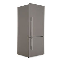
Fisher & Paykel 790 Active Smart Service Manual (145 pages)
Brand:
Fisher & Paykel
| Category:
Refrigerator
| Size: 8.99 MB
Table of Contents
Table of Contents
4
1 Specifications
8
Cabinet Specifications - 230 - 240 Volt
8
Cabinet Specifications - 110 - 115 Volt
10
Compressor Specifications - R134A - 220 - 240 Volt
11
Compressor Specifications - R600A - 220 - 240 Volt
12
Compressor Specifications - R134A - 110 - 115 Volt
13
Model Number Identification - 635 / 680 / 790
14
Model Number Identification - 900
15
Singapore
15
2 Servicing Requirements
16
Specialised Service Tools
16
Static Strap
16
Interface Light Pen Mk 2
16
Health & Safety
16
Good Work Practices
16
Environmental Health and Safety
16
Good Practice and Safety
16
3 Installation Instructions
17
Levelling
17
Door Hinging (Tasman Models Only)
18
Air Space Requirements
18
Temperature Adjustment
18
4 Theory of Operation
19
Terms
19
Internal Air Flow
20
Ice & Water Models
20
Non Ice & Water Models
21
Defrost Cycle
22
R134A System
22
R600A System
23
The Refrigeration Circuit
24
Evaporator
24
Condensate Disposal
25
Filter Drier
25
Internal Condenser
26
Condenser Lay out 635 / 680 / 790 "T" Models
27
Condenser Lay out 635 / 680 / 790 / 900 "B" Models
28
Compressor Compartment Layout
29
Cross Rail
29
Door and Door Hinge
29
Compressor
29
Thermal Fuse
29
Drain Heater Wire
29
Divider Partition
30
LCD Display Panel
31
Door Switches
31
Defrost Heater
31
Low Ambient Heater
32
PC / FC Fans
32
B" Model Fan
32
T" Model PC Fan
33
Interior Light
34
Thermistor Temperature Sensors
35
Basic Operation
36
Temperature Adjustment - Ice & Water Models
36
Temperature Adjustment - Non-Ice & Water Models
36
5 Electronics Section
37
Diagrammatic Overview Function Description
37
Control and Peripheral Functions
38
Power/Control Module
38
Display Module
39
6 Variable Capacity Compressor
40
Variable Capacity Compressor Control Overview
40
Built-In Electronic Protections (Within the Module/Inverter)
40
Compressor Start-Up
40
Overload Detection and Protection
40
Power Limitation (Temperature Protection)
41
Short Circuit Protection
41
VCC Module/Inverter Identification
41
Fault Finding
41
High Voltage Power Supply Circuit
41
Inverter with Diagnostic Function
42
Diagnostic Procedures
42
Testing the VCC3 Inverter (with Diagnostic Function)
44
Equipment Required
47
7 Display Interface - Ice & Water Models
48
Display Functional Schematic
48
Display Interface Features
49
Features
49
Icemaker On/Off
49
Freezer Chill Mode
49
Bottle Chill Mode
49
Water Dispensing
49
Sabbath Mode
50
Key Silent Mode
50
Dispenser Lock
50
Key Lock
50
Filter Replacement Alert
50
Key Presses
51
Temperature Settings
51
8 Icemaker
52
Ice Production
52
Information about the Icemaker
52
Ice bin Full Sequence
52
Safety First
53
Icemaker Fill Tube Heater
53
Pressure Limiting Valve
53
Water Inlet Valves
53
Noises
54
Ice & Water Common Complaints
54
9 Water Dispenser
55
Installation Precautions / Warning
55
Pressure Dispensing Pad
55
Initial Use
55
Water Filter and Cartridge
55
Changing the Water Filter
56
To Reset the Filter Icon
56
To Disable the Filter Alarm
56
10 Diagnostics
57
Ice & Water Models
57
Fault Codes
57
Testing Icemaker Sensor
61
Testing Icemaker Motor
61
Testing Water Valve
62
Diagnostic Modes
63
Input / Output Status
65
Fault History
65
To Manually Force a Defrost
65
LCD Display
65
To Manually Force the Icemaker
66
Data Download
66
Non-Ice & Water Models
67
Fault Codes
67
Diagnostic Mode for Service
70
Sensor Temperature Conversion
70
Input / Output Status
71
Data Download
72
To Manually Force a Defrost
72
Show Room Mode
72
Special Option Mode (Israel)
73
Problem Solving Checklist
74
11 Icemaker & Water Dispenser Service Procedures
75
Component Replacement
75
Icemaker PCB Replacement
75
Icemaker Unit Removal
75
Refitting Icemaker
75
Icemaker Temperature Sensor Replacement
75
Water Valve Replacement
75
Display Module Replacement
76
Water Dispenser Pad Replacement
77
Removing Water Tank
77
Refitting Water Tank
78
Replacing Icemaker Fill Tube Heater
78
Replacing PC Door on Ice & Water Models
81
Designer Doors
81
Classic Doors
84
12 Servicing Procedures
88
Safety Considerations
88
Electrical Safety Test
88
Doors and Door Gaskets
89
Removal of Power/Control Module
89
Initialisation of the Power/Control Module after Installation - Non-Ice & Water Models
90
Freezer Bin, Runner and Air Deflector Removal - E402B and E372B Models
90
FC bin Removal - 900 Models
90
FC Drawer Removal - 900 Models
91
Refitting of the FC Drawer
91
PC Fan Motor - "T" Models
92
PC Fan Motor - "B" Models
92
Defrost Element Replacement
92
Thermal Fuse
92
Cross / Base Rail Door Switches
93
Removal of Display Module - Non-Ice & Water Models
93
PC Sensor Replacement
93
FC Sensor Replacement- "T" and "B" Models
93
FC Sensor Replacement - 900 Models
93
Icemaker Temperature Sensor Replacement
93
Replacement of Low Ambient Heater - "T" Model
94
Replacement of Low Ambient Heater - "B" Models
94
Replacement of Low Ambient Heater - "B" Model (in Return Grill)
94
Interior LED Light Replacement
94
Flapper Element Replacement
95
Block/Edge Connectors
97
Fan Cover Removal Tool (T Models Only)
99
Active Smart ® PC/FC Fan Motor Tester
99
13 Working on the Sealed System
101
Safe Work Practices
101
Leak Detection
101
R600A Operating Pressures
101
Reclaiming
101
Brazing off the System
102
Pressure Testing of the Refrigeration System
102
Transporting of Refrigerators
104
Evaporator Replacement
105
Refilling a Void in Foam Insulation after System Service or Adjustment
105
Polyurethane Foam
106
Safe Practices
106
Removing Back Panel for Access to Water Lines and Joints
107
Embraco Compressor Fitted with External Overload
108
Matsushita "D" Series Compressor Fitted with External Overload and Run Capacitor
109
Compressor Replacement
110
Compressor Fault Diagnosis
111
Compressor Won't Start - Dead (PTC Relay Fitted)
111
Compressor Won't Start - Hums
112
Compressor Starts, Runs and then Stops
112
14 Wiring Diagrams
113
Non Ice & Water Models Power Module Wiring Connections
113
Non-Ice & Water Models Wiring Diagram
114
Ice & Water Models Power Module Wiring Connections
115
Ice & Water Models Wiring Diagram
116
Models Power Module Wiring Connections - Reciprocating Compressor
117
Models Wiring Diagram - Reciprocating Compressor
118
Models Power Module Wiring Connections - VC Compressor
119
Models Wiring Diagram - VC Compressor
120
B" Model Wiring Route
121
T" Model Wiring Route
122
15 Service Reference
123
Service Reference 'B' Models
123
Service Reference 'T' Models
127
16 Fault Finding Flow Chart - Servicing
130
Refrigerator Not Operating
131
No Power to Power/Control Module And/Or Display Module
132
PC/FC Warm
133
Adjust Temperature Settings. Advise Customer Product OK
133
Yes
133
FC too Cold - PC too Warm
134
PC too Cold
135
Ice/Condensation Forming
136
No Light
137
Door Switch Not Operating
138
Defrost Heater Faults
139
Advise Customer
139
Yes
139
Compressor Faults
140
Compressor Runs Continuously
140
Compressor will Not Run and Is Hot to Touch
141
Compressor Electrical Tests
141
Refrigeration System Faults
142
Not Dispensing Water
143
Not Producing Ice
144
Check for
144
Advertisement
Fisher & Paykel 790 Active Smart Service Manual (59 pages)
Brand:
Fisher & Paykel
| Category:
Refrigerator
| Size: 0.86 MB
Table of Contents
Table of Contents
4
1 Terminology
6
2 Specifications
7
Cabinet Specifications
7
Model Number Identification
8
Serial Number Identification
8
3 Servicing Requirements
9
Interface Pen Mk 2
9
Health & Safety
9
Good Work Practices
9
Environmental Health and Safety
9
Good Practice and Safety
9
4 Installation Instructions
10
Levelling
10
Air Space Requirements
11
Temperature Adjustment
11
5 Theory of Operation
12
Internal Air Flow
12
Defrost Cycle
13
The Refrigeration Circuit
14
Servicing Features
15
Condensate Disposal
15
Internal Condenser
16
Cross Rail
19
Divider Partition
19
6 Electronics Section
20
Overview Function Description
20
Control & Peripheral Functions
20
Power/Control Module
20
Display Module
21
Door Switches
21
Compressor
22
Variable Capacity Compressor Control Overview
22
Built-In Electronic Protections (Within the Module/Inverter)
23
Compressor Start-Up
23
Fault Finding
23
High Voltage Power Supply Circuit
23
Overload Detection and Protection
23
Power Limitation (Temperature Protection)
23
Short Circuit Protection
23
Signal Circuit
23
VCC Module/Inverter Identification
23
Defrost Heater
24
Thermal Fuses
25
Low Ambient Heater
25
PC / FC Fans
26
6.1.10 Light
26
6.1.11 Thermistor Temperature Sensors
27
Fault Finding Procedure
28
Fault Code Display Status
28
Diagnostic Mode
31
Sensor Temperature Conversion
31
Input/Output Status
32
Data Download
33
Manual Defrost
33
Show Room Mode
33
Special Option Mode (Israel)
34
Door Gasket - (Integral)
34
7 Removing and Refitting of Components
35
Removal of Power/Control Module
35
PC Sensor Replacement
35
FC Sensor Replacement
35
PC Fan Motor - "T" Model
36
PC Fan Motor - "B" Models
36
Cross / Base Rail Door Reed Switches
36
Defrost Heating Element
36
Removal of Display Module
37
Thermal Fuse
37
Replacement of Interior Lamp
37
Replacement of Low Ambient Heater - "T" Model
37
Replacement of Low Ambient Heater - "B" Model
38
Replacement of Low Ambient Heater - "B" Model (in Return Air Grill)
38
Evaporator Replacement
38
Removal of the FC Evaporator Cover
39
Pressure Testing of the Refrigeration System
40
Transporting of Refrigerators
41
8 Wiring Diagram
42
9 Service Reference
43
B" Models
43
PC too Cold
43
T" Models
46
10 Flow Diagrams
48
Refrigerator Not Operating
48
No Power to Power/Control Module And/Or Display Module
49
PC/FC Warm
50
FC too Cold - PC too Warm
51
PC too Cold
52
Ice/Condensation Forming
53
No Light
54
Refer to Section
54
Door Switch Not Operating
55
Defrost Heater Faults
56
Advise Customer
56
Yes
56
Repair or Replace Faulty Components
56
10.10 Compressor Faults
57
10.11 Compressor Runs Continuously
57
10.12 Compressor will Not Run and Is Hot to Touch
58
10.13 Compressor Electrical Tests
58
10.14 Refrigeration System Faults
59
Advise Customer
59
Temperatures Are
59
Yes
59
Advertisement
Related Products
Fisher & Paykel Active Smart
Fisher & Paykel active smart series
Fisher & Paykel Active Smart E522B
Fisher & Paykel Active Smart E402B
Fisher & Paykel Active Smart RF610A
Fisher & Paykel Active Smart E442B
Fisher & Paykel Active Smart RF201A
Fisher & Paykel Active Smart E331T
Fisher & Paykel Active Smart E372B
Fisher & Paykel Active Smart E381T
Fisher & Paykel Categories
Dishwasher
Cooktop
Refrigerator
Oven
Washer
More Fisher & Paykel Manuals
Login
Sign In
OR
Sign in with Facebook
Sign in with Google
Upload manual
Upload from disk
Upload from URL