Sign In
Upload
Manuals
Brands
Delta Electronics Manuals
Controller
VFD007EL21A
Delta Electronics VFD007EL21A Manuals
Manuals and User Guides for Delta Electronics VFD007EL21A. We have
1
Delta Electronics VFD007EL21A manual available for free PDF download: User Manual
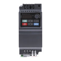
Delta Electronics VFD007EL21A User Manual (210 pages)
VFD-EL Multiple Functions / Micro Type AC Motor Drive
Brand:
Delta Electronics
| Category:
Controller
| Size: 3.81 MB
Table of Contents
Table of Contents
6
Chapter 1 Introduction
12
Receiving and Inspection
13
Nameplate Information
13
Model Explanation
13
Series Number Explanation
14
Drive Frames and Appearances
14
Internal Structure
15
RFI Jumper Location
15
RFI Jumper
16
Remove Instructions
16
Preparation for Installation and Wiring
16
Ambient Conditions
17
Minimum Mounting Clearances
17
Installation with Metal Separation
19
Installation Without Metal Separation
19
DC-Bus Sharing: Connecting the DC-Bus of the AC Motor Drives in Parallel
19
Dimensions
20
General Wiring Information
22
Chapter 2 Installation and Wiring
22
Wiring
23
PNP Mode with External Power
27
External Wiring
29
Main Circuit Connection
30
Output Terminals for Main Circuit
31
Terminals [+, -] for Connecting Brake Resistor
31
Main Circuit Terminals
32
Control Terminals
33
Circuit Diagram for Digital Inputs (NPN Current 16Ma.)
33
The Position of the Control Terminals
33
Terminal Symbols and Functions
33
Analog Inputs (AVI, ACM)
35
Digital Inputs (MI1~MI6, DCM)
35
Description of the Digital Keypad
38
Chapter 3 Keypad and Start up
38
How to Operate the Digital Keypad
40
Reference Table for the 7-Segment LED Display of the Digital Keypad
41
Operation Method
41
Trial Run
42
Chapter 4 Parameters
44
Summary of Parameter Settings
45
Parameter Settings for Applications
64
Description of Parameter Settings
69
Start-Up Display Selection
70
Content of Multi-Function Display
70
User Defined Coefficient K
71
Software Version
71
Password Input
71
Password Set
72
50Hz Base Voltage Selection
73
User-Defined Value 1 (Correspond to Max. Frequency)
73
Maximum Output Frequency (Fmax)
74
Maximum Voltage Frequency (Fbase)
74
Maximum Output Voltage (Vmax)
74
MID-Point Frequency (Fmid)
74
Minimum Output Frequency (Fmin)
75
Minimum Output Voltage (Vmin)
75
Output Frequency Upper Limit
75
Output Frequency Lower Limit
76
Accel/Decel Time Unit
76
Jog Frequency
77
Auto-Acceleration / Deceleration
78
Acceleration/Deceleration S-Curve
79
Source of Second Master Frequency Command
80
Source of First Operation Command
80
Combination of the First and Second Master Frequency Command
81
Stop Method
81
PWM Carrier Frequency Selections
82
Motor Direction Control
84
Line Start Lockout
84
Loss of ACI Signal (4-20Ma)
86
Up/Down Mode
86
Accel/Decel Rate of Change of UP/DOWN Operation with Constant Speed
86
Keypad Frequency Command
87
Communication Frequency Command
87
Initial Frequency Selection (for Keypad & RS485)
87
Initial Frequency Setpoint (for Keypad & RS485)
87
Display the Master Freq Command Source
88
Display the Operation Command Source
88
User-Defined Value 2 Setting
88
User-Defined Value 2
89
Multi-Function Output Relay (RA1, RB1, RC1)
90
Desired Frequency Attained
91
Analog Output Signal (AFM)
92
Analog Output Gain
92
Terminal Count Value
93
Preliminary Count Value
93
EF Active When Terminal Count Value Attained
93
Fan Control
94
Brake Release Frequency
94
Brake Engage Frequency
94
Display the Status of Relay
95
Keypad Potentiometer Bias Polarity
96
Keypad Potentiometer Negative Bias, Reverse Motion Enable/Disable
96
Use of Negative Bias in Noisy Environment
98
Use of Negative Bias in Noisy Environment and Gain Adjustment to Use Full Potentiometer Range
98
Use of 0-10V Potentiometer Signal to Run Motor in FWD and REV Direction
98
Use Negative Slope
99
Multi-Function Input Terminal (MI1, MI2) 2-Wire/ 3-Wire Operation Control Modes
100
Multi-Function Input Contact Selection
104
Digital Terminal Input Debouncing Time
105
Display the Status of Multi-Function Input Terminal
105
Internal/External Multi-Function Input Terminals Selection
106
Internal Terminal Status
107
Multi-Step Speeds Parameters
108
Multi-Speed Via External Terminals
109
Protection Parameters
110
Over-Voltage Stall Prevention
110
Over-Current Stall Prevention During Acceleration
111
Over-Current Stall Prevention During Operation
111
Over-Torque Detection Mode (OL2)
112
Over-Torque Detection Level (OL2)
112
Over-Torque Detection Time (OL2)
112
Electronic Thermal Overload Relay Selection (OL1)
113
Electronic Thermal Characteristic
113
Motor Parameters
116
Motor Rated Current
116
Motor No-Load Current
116
Torque Compensation
116
Accumulative Motor Operation Time (Day)
117
Motor PTC Overheat Protection
117
Motor PTC Overheat Protection Level
117
Treatment of the Motor PTC Overheat
119
Input Debouncing Time of the PTC Protection
119
DC Brake Current Level
120
DC Brake Time During Start-Up
120
DC Brake Time During Stopping
120
Start-Point for DC Brake
120
Momentary Power Loss Operation Selection
121
Maximum Allowable Power Loss Time
121
Base Block Speed Search
121
Baseblock Time for Speed Search (BB)
122
Current Limit for Speed Search
123
Auto Restart after Fault
124
Auto Reset Time at Restart after Fault
124
Automatic Energy-Saving
125
Automatic Voltage Regulation (AVR)
125
Compensation Coefficient for Motor Instability
126
Communication Parameters
127
Communication Address
127
Transmission Speed
127
Transmission Fault Treatment
127
Time-Out Detection
128
Communication Protocol
128
Communication Data Frame
130
Address (Communication Address)
131
Function (Function Code) and DATA (Data Characters)
131
Check Sum
134
Address List
136
Exception Response
139
Communication Program of PC
140
The Explanation of Exception Codes
140
Response Delay Time
141
PID Control
143
PID Set Point Selection
143
Input Terminal for PID Feedback
143
Source of PID Set Point
143
Integral Time
144
Derivative Control
144
Upper Bound for Integral Control
144
Primary Delay Filter Time
145
PID Output Frequency Limit
145
PID Feedback Signal Detection Time
145
Treatment of the Erroneous Feedback Signals (for PID Feedback Error)
146
Gain over the PID Detection Value
146
Detection Time of PID Feedback
146
Wakeup Frequency
146
Minimum PID Output Frequency Selection
148
PID Control Detection Signal Reference
148
PID Calculation Mode Selection
148
Treatment of the Erroneous PID Feedback Level
149
Detection Time of Set Point Deviation Level
149
Offset Level of Liquid Leakage
150
Liquid Leakage Change Detection
150
Time Setting for Liquid Leakage Change
150
Over Current (OC)
152
Chapter 5 Troubleshooting
152
Ground Fault
153
Over Voltage (OV)
153
Low Voltage (Lv)
154
Over Heat (OH1)
155
Overload
155
Keypad Display Is Abnormal
156
Phase Loss (PHL)
156
Motor Cannot Run
157
Motor Speed Cannot be Changed
158
Motor Stalls During Acceleration
159
The Motor Does Not Run as Expected
159
Electromagnetic/Induction Noise
160
Environmental Condition
160
Affecting Other Machines
161
Fault Code Information
162
Common Problems and Solutions
162
Chapter 6 Fault Code Information and Maintenance
162
Reset
166
Maintenance and Inspections
166
Periodical Maintenance
167
Ambient Environment
167
Voltage
167
Keypad
168
Mechanical Parts
168
Cooling Fan of Cooling System
171
Ventilation Channel of Cooling System
171
Appendix A Specifications
172
Appendix B Accessories
176
B.1 All Brake Resistors & Brake Units Used in AC Motor Drives
176
B.1.1 Dimensions and Weights for Brake Resistors
179
B.2 no Fuse Circuit Breaker Chart
182
B.3 Fuse Specification Chart
183
B.4 AC Reactor
184
B.4.1 AC Input Reactor Recommended Value
184
Connected in Input Circuit
185
Correct Wiring
185
B.4.3 Applications
185
B.5 Zero Phase Reactor (RF220X00A)
187
B.6 Remote Controller RC-01
188
B.7 Pu06
189
B.7.1 Description of the Digital Keypad VFD-PU06
189
B.7.2 Explanation of Display Message
189
VFD-PU06 Operation Flow Chart
190
B.8 Fieldbus Modules
191
B.8.1 Devicenet Communication Module (CME-DN01)
191
B.8.1.1 Panel Appearance and Dimensions
191
B.8.1.2 Wiring and Settings
191
B.8.1.3 Power Supply
192
B.8.1.4 Leds Display
192
B.8.2 Lonworks Communication Module (CME-LW01)
192
B.8.2.1 Introduction
192
B.8.2.2 Dimensions
192
Terminal Definition for Lontalk System
193
B.8.2.3 Specifications
193
B.8.2.4 Wiring
193
B.8.2.5 LED Indications
193
B.8.3 Profibus Communication Module (CME-PD01)
194
B.8.3.1 Panel Appearance
194
B.8.3.2 Dimensions
195
B.8.3.3 Parameters Settings in VFD-EL
195
B.8.3.4 Power Supply
195
B.8.3.5 PROFIBUS Address
195
B.8.4 CME-COP01 (Canopen)
196
B.8.4.1 Product Profile
196
B.8.4.2 Specifications
196
Pin Definition on Canopen Connection Port
197
B.8.4.3 Components
197
MAC ID Setting
198
B.8.4.4 LED Indicator Explanation & Troubleshooting
198
B.9 MKE-EP & DIN Rail
200
B.9.1 Mke-Ep
200
B.9.2 DIN Rail: MKEL-DRA (Only for Frame A)
201
Appendix C How to Select the Right Ac Motor Drive
202
Capacity Formulas
203
When One AC Motor Drive Operates One Motor
203
When One AC Motor Drive Operates more than One Motor
203
When It Is Running Continuously
204
Symbol Explanation
204
General Precaution
205
Parameter Settings Note
205
How to Choose a Suitable Motor
206
Power Transmission Mechanism
208
Motor Torque
208
Advertisement
Advertisement
Related Products
Delta Electronics VFD007V23A/43A-2
Delta Electronics VFD007EL23A
Delta Electronics VFD007EL43A
Delta Electronics VFD007EL11A
Delta Electronics VFD002EL11A
Delta Electronics VFD002EL21A
Delta Electronics VFD002EL23A
Delta Electronics VFD004EL11A
Delta Electronics VFD004EL21A
Delta Electronics VFD004EL23A
Delta Electronics Categories
Power Inductor
Power Supply
Computer Hardware
Fan
Transceiver
More Delta Electronics Manuals
Login
Sign In
OR
Sign in with Facebook
Sign in with Google
Upload manual
Upload from disk
Upload from URL