Sign In
Upload
Manuals
Brands
Delta Manuals
Controller
DVP-15MC Series
Delta DVP-15MC Series Manuals
Manuals and User Guides for Delta DVP-15MC Series. We have
1
Delta DVP-15MC Series manual available for free PDF download: Operation Manual
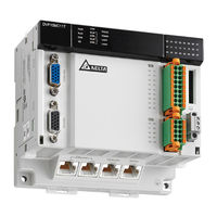
Delta DVP-15MC Series Operation Manual (972 pages)
Motion Controller
Brand:
Delta
| Category:
Controller
| Size: 14.25 MB
Table of Contents
Table of Contents
2
Chapter 1 Preface
16
Explanation of Symbols in this Manual
17
Revision History
18
Chapter 2 Overview
20
Product Description
21
Functions
21
Profile and Components
22
Chapter 3 Specifications
24
Specifications
24
3.1.2 Devices and Data Types
26
Devices
26
Valid Ranges of Devices
27
Latched Devices
28
Data Types and Valid Ranges Supported
28
3.2 Electrical Specifications
29
Chapter 4 System Architecture
33
System Constitution
33
Power Supply
33
Left-Side Extension
33
Connectable Left-Side Extension Module
33
Connectable Right-Side Extension Modules
34
Allocation of Left-Side Network Module Addresses
34
Method of Reading/Writing of Left-Side Modules
34
Right-Side Extension
34
Allocation of Right-Side Extension Module Addresses
35
Connectable Servo Drives
36
SD Memory Card
38
Model and Specification
38
Chapter 5 Installation
41
Dimensions
41
Profile and Dimensions
41
Dimensions of Left-Side and Right-Side Extension Modules
41
Connecting to the Left-Side Extension Module
42
Connecting to the Right-Side Extension Module
44
Installing and Removing the SD Card
45
Installing the Module in the Control Cabinet
47
Installing the Module to DIN Rail
47
Illustration of Installation Inside the Control Cabinet
47
Environmental Temperature in the Control Cabinet
48
Actions for Anti-Interference
48
Dimension Requirement in the Control Cabinet
49
Chapter 6 Wiring, Communication Setting and Network Construction
50
Wiring
52
Power Supply
52
Safety Circuit Wiring
53
Input Point and Output Point Wiring
55
Function that Input Points Support
55
Input Point Wiring
56
Output Point Wiring
58
RS-485 Communication Port
59
Function that RS-485 Port Supports
59
Definitions of RS-485 Port Pins
59
RS-485 Hardware Connection
59
Supported Function Codes and Exception Codes
60
Communication Port
62
Function that RS-232 Port Supports
62
Definitions of RS-232 Port Pins
62
RS-232 Hardware Connection
62
Supported Function Codes and Exception Codes
63
SSI Absolute Encoder Port
64
Function of SSI Absolute Encoder
64
Definitions of SSI Port Pins
64
SSI Absolute Encoder Hardware Connection
65
Incremental Encoders
66
Function of Incremental Encoder
66
Definition of Incremental Encoder Port Pins
66
Incremental Encoder Hardware Connection
67
Ethernet Communication Port
68
Function that Ethernet Communication Port Supports
68
Pins of Ethernet Communication Port
69
Network Connection of Ethernet Communication Port
69
Function Codes that Ethernet Communication Port Supports
69
Motion Communication Port
71
Function that Motion Communication Port Supports
71
Pins of Motion Communication Port
71
Motion Network Connection
71
Communication Speed and Communication Distance
71
Canopen Communication Port
72
Functions that Canopen Communication Port Supports
72
Pins of Canopen Communication Port
73
PDO Mapping at Canopen Communication Port
73
Network Connection at Canopen Communication Port
73
Canopen Communication Rate and Communication Distance
74
Chapter 7 Execution Principle
77
Tasks
77
Task Types
77
Priority Levels of Tasks
79
Watchdog for a Task
81
Motion and Communication Instructions for each Task Type
82
The Impact of PLC RUN or STOP on Variables and Devices
85
Relationship between Motion Program and Motion Bus
85
Synchronization Cycle Period Setting
86
Chapter 8 Logic Instructions
92
Table of Logic Instructions
92
Explanation of Logic Instructions
96
R_Trig
96
Sequence Input /Output Instructions
96
F_Trig
99
Sema
104
Sequence Control Instructions
106
Jmp
106
Data Movement Instructions
107
Move
112
Movedigit
113
Exchange
114
Swap
116
Comparison Instructions
118
Timer Instructions
130
Trunc
198
Floor
200
Fraction
202
And
204
Bit String Instructions
204
No T
210
Xor
212
Xorn
215
Shift Instructions
218
Shl
218
Shr
220
Rol
222
Ro R
224
Max
226
Selection Instructions
226
Min
228
Sel
231
Mux
232
Limit
234
Band
236
Zone
239
Bool_To_
242
Data Type Conversion Instructions
242
Bit Strings_To_
245
Real Numbers_To_
245
Times,Dates_To_
264
Strings_To_
266
Communication Instructions
269
Dmc_Readparameter_Canopen
270
Dmc_Writeparameter_Canopen
274
Eth_Link_Config
278
Eth_Link_Manage
288
Eth_Link_Status
288
Eth_Link_Config_Ext
294
ETH_ Setserverlinkkeeptime
296
Eth_Socket_Manage
297
Eth_Socket_Config
299
Eth_Socket_Open
302
Eth_Socket_Send
304
Eth_Socket_Receive
308
Eth_Socket_Close
312
Eth_Socket_Status
314
Ehternet Free Protocol Example
317
Rs485_Link_Manage
322
Rs485_Link_Config
324
Rs485_Link_Status
328
RS485 Data Exchange Example
331
Rs485_Rs
334
RS485 Free Protocol Example
340
Rs485_Setdelaytime
343
Rs232_Link_Manage
345
Rs232_Link_Config
347
Rs232_Link_Status
351
RS232 Data Exchange Example
354
Rs232_Rs
357
RS232 Free Protocol Example
363
Rs232_Setdelaytime
366
String Processing Instructions
368
Concat
369
Delete
370
Insert
373
Left / Right
374
MID
377
Replace
378
Len
380
Fi Nd
381
Immediate Refresh Instructions
383
From
385
Immediateinput
391
Immediateoutput
393
Left_Manage
395
PID-Related Instructions
399
Pid
400
Gpwm
411
Address Instruction
412
Adr
412
Canmotion_Sysdiag (Motion System Diagnosis)
414
Network Diagnosis
414
Canmotion_Nodediag (Motion Axis Diagnosis)
416
Canopen_Sysdiag (Canopen System Diagnosis)
418
Canopen_Nodediag (Canopen Slave Diagnosis)
420
Canopen_State (Canopen Master Diagnosis)
422
Read and Write Offset Bit Value
424
Setbitoffsetvalue
424
Getbitoffsetvalue
426
FCS Instructions
428
Crc
429
Lrc
430
Chapter 9 Introductions of Axis Parameters
433
Description of Axis Parameters
434
And ENO
438
Relation Among Velocity, Acceleration and Jerk
439
Chapter 10 Motion Control Function
439
Introduction of Buffermode
442
The State Machine
468
Chapter 11 Motion Control Instructions
474
11.1 Table of Motion Control Instructions
474
11.2 about Motion Control Instructions
476
Composition of a Motion Control Instruction
476
Configuration of Motion Control Instructions
476
Program Languages that Motion Control Instructions Support
476
11.3 Single-Axis Instructions
477
Mc_Power
477
Mc_Home
486
Mc_Movevelocity
491
Mc_Halt
498
Mc_Stop
503
Mc_Moverelative
508
Mc_Moveadditive
516
Mc_Moveabsolute
524
Mc_Movesuperimposed
533
Mc_Haltsuperimposed
540
Mc_Setposition
545
Mc_Setoverride
556
Mc_Reset
560
Dmc_Settorque
563
Mc_Readaxiserror
567
Mc_Readactualposition
569
Mc_Readstatus
574
Mc_Readmotionstate
579
Dmc_Readparameter_Motion
584
Dmc_Writeparameter_Motion
587
Dmc_Writeparameter_Motion
589
Dmc_Touchprobe
593
Dmc_Touchprobecyclically
602
Dmc_Jog
606
Dmc_Movevelocitystopbypos
608
Dmc_Movevelocitystopbylinepos
612
Dmc_Readpositionlagstatus
616
Dmc_Writepositionlagsetting
619
Dmc_Changemechanismgearratio
621
Dmc_Torquecontrol
623
Dmc_Movevelocity
628
Dmc_Switchsoftlimit
629
11.4 Multi-Axis Instructions
631
Mc_Gearin
631
Mc_Gearout
637
Mc_Combineaxes
641
Introduction of Electronic Cam
649
Mc_Camin
650
Mc_Camout
671
Dmc_Camreadpoint
677
Dmc_Camwritepoint
681
Dmc_Camset
685
Dmc_Camreadtappetstatus
687
Dmc_Camreadtappetvalue
692
Dmc_Camwritetappetvalue
695
Dmc_Camdeletetappet
703
11.5 Application Instructions
706
Rotary Cut Technology
706
Rotary Cut Parameters
707
Control Feature of Rotary Cut Function
708
Introduction to Cam Curve with Rotary Cut Function
709
Apf_Rotarycut_Init
713
Rotary-Cut Instructions
713
Apf_Rotarycut_In
716
Application Example of Rotary Cut Instructions
720
11.6 G Code Instructions
724
G Code Input Format
724
Explanation of G Code Formats
726
G Code Functions
728
G90 (Absolute Mode)
728
G91 (Relative Mode)
729
G0 (Rapid Positioning)
730
G1 (Linear Interpolation)
733
G2 (Clockwise Circular/ Helical Interpolation)
737
G3 (Anticlockwise Circular /Helical Interpolation)
744
G17/G18/G19 (Specify Circular Interpolation Plane)
750
G4 (Dwell Instruction)
751
G50 (Precise Stop)
752
G51 (Round Path Transition)
753
G52 (Smooth Path Transition)
754
M Code
756
Dmc_Cartesiancoordinate
758
G Code Instruction
758
Dmc_Readmfunction
764
Dmc_Resetmfunction
767
Dmc_Setg0Para
770
Dmc_Setg1Para
773
Dmc_Setstartposition
776
11.7 Axes Group Instructions
779
Dmc_Addaxistogroup
779
Dmc_Removeaxisfromgroup
781
Dmc_Ungroupallaxes
783
Dmc_Groupenable
791
Dmc_Groupstop
791
Dmc_Groupinterrupt
794
Dmc_Groupcontinue
799
Dmc_Movedirectabsolute
801
Dmc_Movedirectrelative
806
Dmc_Movelinearabsolute
811
Dmc_Movelinearrelative
824
Dmc_Movecircularabsolute
837
Dmc_Movecircularrelative
848
Dmc_Groupsetoverride
859
Dmc_Groupreadactualposition
864
11.8 Coordination Instructions
866
Dmc_Controlaxisbypos
870
Dmc_Nc
871
Chapter12 Troubleshooting
881
Table of Error Ids in Motion Instructions
886
System Trouble Diagnosis through System Error Codes
897
Appendix A Modbus Communication
906
Message Format in ASCII Mode
906
Message Format in RTU Mode
909
Modbus Function Codes Supported
911
Modbus Exception Response Code Supported
911
Introduction to Modbus Function Codes
912
Table of Registers and Corresponding Modbus Addresses
919
Appendix B Modbus TCP Communication
923
Exception Response Code in Modbus TCP
923
Modbus Function Codes in Modbus TCP
923
Appendix C Canopen Protocol
935
Node States
936
Network Management (NMT
938
PDO (Process Data Object
938
Appendix D Explanation of Homing Modes
943
Explanation of Homing Modes
945
Appendix E List of Accessories
969
Accessories for PROFIBUS DP Communication
970
Accessories for Devicenet Communication
970
Advertisement
Advertisement
Related Products
Delta DVP15MC11T
Delta DVP15MC11T-06
Delta DVP-10PM
Delta DVP12SE11R
Delta DVP12SE11T
Delta DVP16SP11R
Delta DVP16SP11T
Delta DVP14SS211R
Delta DVP14SS211T
Delta DVP12SS211S
Delta Categories
Plumbing Product
Kitchen & Bath Fixtures
Bathroom Fixtures
Saw
Power Supply
More Delta Manuals
Login
Sign In
OR
Sign in with Facebook
Sign in with Google
Upload manual
Upload from disk
Upload from URL