Sign In
Upload
Manuals
Brands
Daikin Manuals
Air Conditioner
J Series
Daikin J Series Manuals
Manuals and User Guides for Daikin J Series. We have
6
Daikin J Series manuals available for free PDF download: Service Manual, Engineeiring Data, Operation Manual
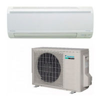
Daikin J Series Service Manual (268 pages)
Brand:
Daikin
| Category:
Air Conditioner
| Size: 10.34 MB
Table of Contents
Table of Contents
3
Introduction
7
Safety Cautions
7
Used Icons
11
Part 1 List of Functions
12
Functions
13
Cooling Only
13
Heat Pump
14
Part 2 Specifications
15
Specifications
16
Cooling Only
16
Heat Pump
18
Part 3 Printed Circuit Board Connector Wiring Diagram
21
Indoor Unit
22
Outdoor Unit
25
Rk(X)S20/25/35J2V1B
25
Rk(X)S42J2V1B
27
Rk(X)S50J2V1B
29
Part 4 Function and Control
31
Main Functions
32
Temperature Control
32
Frequency Principle
32
Airflow Direction Control
34
Fan Speed Control for Indoor Units
35
Program Dry Operation
36
Automatic Operation
37
Thermostat Control
38
NIGHT SET Mode
39
ECONO Operation
40
2-Area INTELLIGENT EYE Operation
41
Inverter POWERFUL Operation
43
Other Functions
44
Function of Thermistor
45
Control Specification
46
Mode Hierarchy
46
Frequency Control
47
Controls at Mode Changing / Start-Up
49
Discharge Pipe Temperature Control
51
Input Current Control
52
Freeze-Up Protection Control
53
Heating Peak-Cut Control
53
Outdoor Fan Control
54
Liquid Compression Protection Function
54
Defrost Control
55
Electronic Expansion Valve Control
56
Malfunctions
59
Part 5 Operation Manual
60
System Configuration
61
Operation Manual
62
Remote Controller
62
AUTO · DRY · COOL · HEAT · FAN Operation
63
Adjusting the Airflow Direction
65
COMFORT AIRFLOW and INTELLIGENT EYE Operation
67
POWERFUL Operation
71
OUTDOOR UNIT QUIET Operation
72
ECONO Operation
73
OFF TIMER Operation
74
ON TIMER Operation
75
WEEKLY TIMER Operation
76
Part 6 Service Diagnosis
84
Troubleshooting with LED
86
Indoor Unit
86
Outdoor Unit
86
Problem Symptoms and Measures
87
Service Check Function
88
ARC452 Series
88
Troubleshooting
91
Error Codes and Description
91
Indoor Unit PCB Abnormality
92
Freeze-Up Protection Control or Heating Peak-Cut Control
93
Fan Motor (DC Motor) or Related Abnormality
95
Thermistor or Related Abnormality (Indoor Unit)
97
Signal Transmission Error (between Indoor Unit and Outdoor Unit)
98
Unspecified Voltage (between Indoor Unit and Outdoor Unit)
99
Outdoor Unit PCB Abnormality
100
OL Activation (Compressor Overload)
103
Compressor Lock
104
DC Fan Lock
105
Input Overcurrent Detection
106
Four Way Valve Abnormality
107
Discharge Pipe Temperature Control
109
High Pressure Control in Cooling
111
Compressor System Sensor Abnormality
112
Position Sensor Abnormality
114
DC Voltage / Current Sensor Abnormality (20/25/35/42 Class)
117
CT or Related Abnormality (50 Class)
118
Thermistor or Related Abnormality (Outdoor Unit)
120
Electrical Box Temperature Rise
122
Radiation Fin Temperature Rise
124
Output Overcurrent Detection
126
Refrigerant Shortage
128
Low-Voltage Detection or Over-Voltage Detection
131
Signal Transmission Error on Outdoor Unit PCB (50 Class Only)
133
Check
134
Fan Motor Connector Output Check
134
Electronic Expansion Valve Check
134
Four Way Valve Performance Check
135
Thermistor Resistance Check
136
Installation Condition Check
137
Discharge Pressure Check
137
Outdoor Fan System Check
138
Power Supply Waveforms Check
138
Inverter Units Refrigerant System Check
138
Capacitor Voltage Check
139
Power Module Check
139
Inverter Checker" Check
140
Rotation Pulse Check on the Outdoor Unit PCB
142
Main Circuit Short Check
143
Part 7 Removal Procedure
144
Indoor Unit
145
Removal of Air Filters
145
Removal of Front Panel
147
Removal of Front Grille
149
Removal of Horizontal Blades / Vertical Blades
152
Removal of Electrical Box
155
Removal of Pcbs
158
Removal of Indoor Heat Exchanger
163
Removal of Swing Motors
166
Removal of Fan Motor
170
Outdoor Unit - RK(X)S20/25/35J2V1B
173
Removal of Outer Panels / Fan Motor
173
Removal of Electrical Box
182
Removal of Pcbs
185
Removal of Reactor / Partition Plate
193
Removal of Sound Blankets
195
Removal of Four Way Valve
197
Removal of Compressor
200
Outdoor Unit - RK(X)S42J2V1B
202
Removal of Outer Panels
202
Removal of Electrical Box
204
Removal of PCB
209
Removal of Sound Blankets
214
Removal of Outdoor Fan / Fan Motor
216
Removal of Thermistors
219
Removal of Four Way Valve / Electronic Expansion Valve
220
Removal of Compressor
223
Outdoor Unit - RK(X)S50J2V1B
226
Removal of Outer Panels
226
Removal of Outdoor Fan / Fan Motor
230
Removal of Electrical Box
234
Removal of PCB
239
Removal of Sound Blankets / Thermistors
242
Removal of Four Way Valve
244
Removal of Electronic Expansion Valve
245
Removal of Compressor
246
Part 8 Trial Operation and Field Settings
249
Pump down Operation
250
Forced Cooling Operation
251
Trial Operation
253
Field Settings
254
Model Type Setting
254
When 2 Units Are Installed in 1 Room
254
Standby Electricity Saving
255
Facility Setting Jumper and Switch (Cooling at Low Outdoor Temperature)
256
Jumper and Switch Settings
257
Application of Silicon Grease to a Power Transistor and a Diode Bridge
258
Part 9 Appendix
259
Piping Diagrams
260
Indoor Unit
260
Outdoor Unit
261
Wiring Diagrams
265
Indoor Unit
265
Outdoor Unit
265
Advertisement
Daikin J Series Service Manual (192 pages)
Brand:
Daikin
| Category:
Heat Pump
| Size: 6.63 MB
Table of Contents
Table of Contents
3
Introduction
6
Safety Cautions
6
Used Icons
10
Part 1 List of Functions
11
Functions
12
Part 2 Specifications
13
Specifications
14
Part 3 Printed Circuit Board Connector Wiring Diagram
16
Printed Circuit Board Connector Wiring Diagram
17
Indoor Unit
17
Outdoor Unit
20
Part 4 Function and Control
22
Main Functions
23
Frequency Principle
23
Operation Starting Control
25
Airflow Direction Control
26
Fan Speed Control for Indoor Units
27
Program Dry Operation
28
Automatic Operation
29
Thermostat Control
30
NIGHT SET Mode
31
ECONO Operation
32
INTELLIGENT EYE Operation
33
Inverter POWERFUL Operation
34
Other Functions
36
Function of Thermistor
37
Control Specification
38
Mode Hierarchy
38
Frequency Control
39
Controls at Mode Changing / Start-Up
41
Discharge Pipe Temperature Control
42
Input Current Control
43
Freeze-Up Protection Control
44
Heating Peak-Cut Control
44
Outdoor Fan Control
45
Liquid Compression Protection Function
45
Defrost Control
46
Electronic Expansion Valve Control
47
Malfunctions
50
Forced Operation Mode
51
Standby Electricity Saving
51
Part 5 Operation Manual
52
System Configuration
53
Operation Manual
54
Name of Parts
54
AUTO · DRY · COOL · HEAT · FAN Operation
58
Adjusting the Airflow Direction and Rate
60
COMFORT AIRFLOW Operation
62
INTELLIGENT EYE Operation
63
POWERFUL Operation
65
OUTDOOR UNIT QUIET Operation
66
ECONO Operation
67
OFF TIMER Operation
68
ON TIMER Operation
69
WEEKLY TIMER Operation
70
Part 6 Service Diagnosis
76
Caution for Diagnosis
77
Troubleshooting with LED
77
Problem Symptoms and Measures
78
Service Check Function
79
Troubleshooting
82
Error Codes and Description
82
Indoor Unit PCB Abnormality
83
Freeze-Up Protection Control or Heating Peak-Cut Control
84
Fan Motor (DC Motor) or Related Abnormality
86
Thermistor or Related Abnormality (Indoor Unit)
88
Front Panel Open / Close Fault
89
Signal Transmission Error (between Indoor Unit and Outdoor Unit)
90
Unspecified Voltage (between Indoor Unit and Outdoor Unit)
91
Outdoor Unit PCB Abnormality
92
OL Activation (Compressor Overload)
93
Compressor Lock
94
DC Fan Lock
95
Input Overcurrent Detection
96
Four Way Valve Abnormality
97
Discharge Pipe Temperature Control
99
High Pressure Control in Cooling
100
Compressor System Sensor Abnormality
102
Position Sensor Abnormality
103
DC Voltage / Current Sensor Abnormality
105
Thermistor or Related Abnormality (Outdoor Unit)
106
Electrical Box Temperature Rise
108
Radiation Fin Temperature Rise
110
Output Overcurrent Detection
112
Refrigerant Shortage
114
Low-Voltage Detection or Over-Voltage Detection
116
Check
117
How to Check
117
Part 7 Removal Procedure
124
Indoor Unit
125
Removal of Air Filter / Front Panel
125
Removal of Horizontal Blades
129
Removal of Front Grille
131
Removal of Front Panel Mechanism ASSY
134
Removal of Display Lens ASSY
136
Removal of Reduction Motor / Limit Switch
137
Removal of Fan Guard / Electrical Box
139
Removal of PCB
142
Removal of Swing Motor
148
Removal of Lndoor Heat Exchanger
149
Removal of Fan Rotor / Fan Motor
152
Removal of Vertical Blade ASSY
155
Outdoor Unit
156
Removal of Outer Panels / Fan Motor
156
Removal of Electrical Box
165
Removal of PCB
168
Removal of Reactor / Partition Plate
176
Removal of Sound Blanket
178
Removal of Four Way Valve
180
Removal of Compressor
183
Part 8 Others
186
Others
186
Trial Operation
186
Field Settings
187
Application of Silicon Grease to a Power Transistor and a Diode Bridge
188
Part 9 Appendix
189
Piping Diagrams
190
Indoor Unit
190
Outdoor Unit
190
Wiring Diagrams
191
Indoor Unit
191
Outdoor Unit
191
Daikin J Series Service Manual (158 pages)
Inverter Pair Wall Mounted Type
Brand:
Daikin
| Category:
Inverter
| Size: 9.01 MB
Table of Contents
Table of Contents
3
Introduction
6
Safety Cautions
6
Used Icons
10
Part 1 List of Functions
11
Functions
12
Part 2 Specifications
13
Specifications
14
Part 3 Printed Circuit Board Connector Wiring Diagram
15
Printed Circuit Board Connector Wiring Diagram
16
Indoor Unit
16
Outdoor Unit
18
Part 4 Function and Control
20
Main Functions
21
Frequency Principle
21
Airflow Direction Control
23
Fan Speed Control for Indoor Units
24
Program Dry Operation
25
Automatic Operation
26
Thermostat Control
27
NIGHT SET Mode
28
ECONO Operation
29
Inverter POWERFUL Operation
30
Other Functions
31
Control Specification
32
Function of Thermistor
32
Mode Hierarchy
33
Frequency Control
34
Controls at Mode Changing / Start-Up
36
Discharge Pipe Temperature Control
37
Input Current Control
38
Freeze-Up Protection Control
39
Heating Peak-Cut Control
39
Outdoor Fan Control
40
Liquid Compression Protection Function
40
Defrost Control
41
Malfunctions
42
Forced Operation Mode
43
Part 5 Operation Manual
44
System Configuration
45
Operation Manual
46
Remote Controller
46
AUTO · DRY · COOL · HEAT · FAN Operation
47
Adjusting the Airflow Direction
49
COMFORT AIRFLOW Operation
51
POWERFUL Operation
52
ECONO Operation
53
OFF TIMER Operation
54
ON TIMER Operation
55
Part 6 Service Diagnosis
56
Caution for Diagnosis
57
Troubleshooting with LED
57
Problem Symptoms and Measures
58
Service Check Function
59
Troubleshooting
62
Error Codes and Description
62
Indoor Unit PCB Abnormality
63
Freeze-Up Protection Control or Heating Peak-Cut Control
64
Fan Motor (DC Motor) or Related Abnormality
66
Thermistor or Related Abnormality (Indoor Unit)
68
Signal Transmission Error (between Indoor and Outdoor Unit)
69
Unspecified Voltage (between Indoor and Outdoor Unit)
70
Outdoor Unit PCB Abnormality
71
OL Activation (Compressor Overload)
72
Compressor Lock
73
Input Overcurrent Detection
74
Four Way Valve Abnormality
75
Discharge Pipe Temperature Control
77
High Pressure Control in Cooling
78
Compressor System Sensor Abnormality
80
Position Sensor Abnormality
81
DC Voltage / Current Sensor Abnormality
83
Thermistor or Related Abnormality (Outdoor Unit)
84
Electrical Box Temperature Rise
86
Radiation Fin Temperature Rise
88
Output Overcurrent Detection
90
Refrigerant Shortage
92
Low-Voltage Detection or Over-Voltage Detection
94
Check
95
How to Check
95
Thermistor Resistance Check
96
Installation Condition Check
97
Discharge Pressure Check
97
Main Circuit Short Check
103
Part 7 Removal Procedure
104
Indoor Unit
105
Removal of Air Filter
105
Removal of Horizontal Blade
107
Removal of Front Panel
109
Removal of Front Grille
110
Removal of Electrical Box / Vertical Blades
112
Removal of Swing Motor / PCB
117
Removal of Indoor Heat Exchanger
121
Removal of Fan Rotor / Fan Motor
124
Exchange of Drain Hose
127
Outdoor Unit
128
Removal of Panels
128
Removal of Outdoor Fan / Fan Motor
130
Removal of Electrical Box / PCB
132
Removal of Sound Blanket
144
Removal of Four Way Valve
146
Removal of Compressor
149
Part 8 Others
151
Others
151
Trial Operation
151
Field Settings
152
Application of Silicon Grease to a Power Transistor and a Diode Bridge
153
Part 9 Appendix
154
Piping Diagrams
155
Indoor Unit
155
Outdoor Unit
155
Wiring Diagrams
156
Indoor Unit
156
Outdoor Unit
157
Advertisement
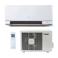
Daikin J Series Engineeiring Data (98 pages)
J-Series Split Cooling Only / Heat Pump
Brand:
Daikin
| Category:
Air Conditioner
| Size: 29.65 MB
Table of Contents
Table of Contents
2
The Single Split Duct-Free System
4
1 Power Supply
4
Ftkn09Jevju Rkn09Jevju Ftkn12Jevju Rkn12Jevju Ftxn09Jevju Rxn09Jevju Ftxn12Jevju Rxn12Jevju
4
2 Functions
5
3 Specifications
6
Cooling Only
6
Heat Pump
7
4 Dimensions
8
Indoor Units
8
Outdoor Units
9
5 Wiring Diagrams
10
Indoor Units
10
Outdoor Units
10
6 Piping Diagrams
11
Indoor Units
11
Outdoor Units
12
7 Capacity Tables
13
Cooling Only
13
Heat Pump
15
Capacity Correction Factor by the Length of Refrigerant Piping (Reference)
19
8 Operation Limit
20
9 Sound Level
21
Measuring Location
21
Octave Band Level
22
10 Electric Characteristics
24
11 Installation Manual
25
Indoor Units - Safety Considerions
25
Indoor Unit Installation Instructions
27
Preparation before Installation
28
Indoor Unit Installation
30
Installing Indoor Unit
31
Left-Side, Left-Back, or Left-Bottom Piping
32
How to Replace the Drain Plug and Drain Hose
32
Drain Piping
35
Refrigerant Piping
36
Outdoor Units - Safety Considerions
38
Outdoor Units Installation Instructions
40
Outdoor Unit Installation Drawings
41
Installation Guidelines
42
Precautions on Installation
42
Installing Outdoor Unit
42
Outdoor Unit Installation
43
Purging Air and Checking Gas Leakage
44
Refrigerant Piping Work
45
Pump down Operation
46
12 Operation Manual
50
Safety Considerations
50
Operation Instructions
53
13 Optional Accessories
78
Option List
78
BRC944B2> Wired Remote Controller
79
Preparation before Operation
82
Setting the Current Time
82
Adjusting Airflow Direction
86
Timer Operation
88
Daily Timer
91
Cleaning the Remote Controller
92
KRP980B1> Interface Adaptor for Wired Remote Controller
93
Removing Electrical Component Box
95
KPW937A4> Air Direction Adjustment Grille
97
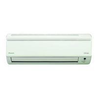
Daikin J Series Engineeiring Data (96 pages)
J-Series Cooling Only/Heat Pump
Brand:
Daikin
| Category:
Air Conditioner
| Size: 35.29 MB
Table of Contents
Table of Contents
2
The Single Split Duct-Free System
4
1 Power Supply
4
Ftks09Jevju Rks09Jevju Ftks12Jevju Rks12Jevju Ftxs09Jevju Rxs09Jevju Ftxs12Jevju Rxs12Jevju
4
2 Functions
5
3 Specifications
6
Cooling Only
6
Heat Pump
7
4 Dimensions
8
Indoor Units
8
Outdoor Units
9
5 Wiring Diagrams
10
Indoor Units
10
Outdoor Units
10
6 Piping Diagrams
11
Indoor Units
11
Outdoor Units
12
7 Capacity Tables
13
Cooling Only
13
Heat Pump
15
Capacity Correction Factor by the Length of Refrigerant Piping
19
8 Operation Limit
20
9 Sound Level
21
Measuring Location
21
Octave Band Level
22
10 Electric Characteristics
24
11 Installation Manual
25
Indoor Units
25
Choosing an Installation Site
26
Indoor Unit
26
Wireless Remote Controller
26
Preparation before Installation
27
Indoor Unit Installation Drawings
28
Indoor Unit Installation
29
Installing Indoor Unit
30
Left-Side, Left-Back, or Left-Bottom Piping
31
How to Replace the Drain Plug and Drain Hose
31
Drain Piping
34
Refrigerant Piping
35
Outdoor Units
37
Safety Precautions
38
Outdoor Unit Installation Drawings
40
Installation Guidelines
41
Precautions on Installation
41
Installing Outdoor Unit
41
Outdoor Unit Installation
42
Purging Air and Checking Gas Leakage
43
Refrigerant Piping Work
44
Pump down Operation
45
12 Safety Considerations
49
13 Optional Accessories
76
Option List
76
BRC944B2> Wired Remote Controller
77
Preparation before Operation
80
Setting the Current Time
80
Adjusting Airflow Direction
84
Timer Operation
86
Daily Timer
89
KRP980B1> Interface Adaptor for Wired Remote Controller
91
Removing Electrical Component Box
93
KPW937A4> Air Direction Adjustment Grille
95
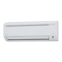
DAIKIN J Series Operation Manual (18 pages)
Brand:
DAIKIN
| Category:
Air Conditioner
| Size: 0.41 MB
Table of Contents
Operation Manual
1
Safety Precautions
1
Installation
2
Names of Parts
3
Indoor Unit
3
Outdoor Unit Parts/Remote Controller Overview
4
Preparation before Operation
5
Setting the Clock
6
Tips for Saving Energy
6
Auto · Dry · Cool · Heat · Fan Operation
7
Powerful Operation
8
Note for Multi System
8
Adjusting the Air Flow Direction
9
Adjusting the Louvre
9
Adjusting the Horizontal Blade (Flap)
9
Off Timer Operation
10
ON TIMER Operation
10
To Cancel the Timer
10
Good Sleep Cooling Operation
11
Intelligent Eye
12
Care and Cleaning
13
Cleaning the Air Filters
13
Replacing Air Purifying Filters
13
Cleaning the Front Grille
14
Before a Long Idle Period
14
Troubleshooting
15
Advertisement
Related Products
Daikin JEHSCU0250M1/3
Daikin JEHSCU0400M3
Daikin JEHSCU0300M1/3
Daikin JEHSCU0500M3
Daikin JEHSCU0680M3
Daikin JEHSCU1000M3
Daikin JEHSCU0400L3
Daikin JEHSCU0500L3
Daikin JEHSCU0600L3
Daikin JEHSCU0750L3
Daikin Categories
Air Conditioner
Heat Pump
Remote Control
Chiller
Fan
More Daikin Manuals
Login
Sign In
OR
Sign in with Facebook
Sign in with Google
Upload manual
Upload from disk
Upload from URL