Table of Contents
Advertisement
Operator's Manual
SAE-300
Register your machine:
www.lincolnelectric.com/register
Authorized Service and Distributor Locator:
www.lincolnelectric.com/locator
Save for future reference
Date Purchased
Code: (ex: 10859)
Serial: (ex: U1060512345)
IM10209
| Issue D ate Mar-15
© Lincoln Global, Inc. All Rights Reserved.
®
MP
For use with machines having Code Numbers:
12268
Need Help? Call 1.888.935.3877
to talk to a Service Representative
Hours of Operation:
8:00 AM to 6:00 PM (ET) Mon. thru Fri.
After hours?
Use "Ask the Experts" at lincolnelectric.com
A Lincoln Service Representative will contact you
no later than the following business day.
For Service outside the USA:
Email: globalservice@lincolnelectric.com
Advertisement
Table of Contents
Troubleshooting

Related Manuals for Lincoln Electric SAE-300 MP


Summary of Contents for Lincoln Electric SAE-300 MP
- Page 1 Operator’s Manual ® SAE-300 For use with machines having Code Numbers: 12268 Need Help? Call 1.888.935.3877 Register your machine: to talk to a Service Representative www.lincolnelectric.com/register Authorized Service and Distributor Locator: Hours of Operation: www.lincolnelectric.com/locator 8:00 AM to 6:00 PM (ET) Mon. thru Fri. Save for future reference After hours? Use “Ask the Experts”...
-
Page 2: Safety Precautions
THANK YOU FOR SELECTING A QUALITY PRODUCT BY KeeP your head out oF the Fumes. LINCOLN ELEC TRIC. DON’T get too close to the arc. Use corrective lenses if necessary to stay a reasonable distance away from the arc. READ and obey the Material Safety Please examine Carton and equiPment For Data Sheet (MSDS) and the warning damage immediately... -
Page 3: California Proposition 65 Warnings
American Welding Society, P.O. Box 351040, Miami, Florida 33135 or ELECTRIC AND CSA Standard W117.2-1974. A Free copy of “Arc Welding Safety” MAGNETIC FIELDS MAY booklet E205 is available from the Lincoln Electric Company, 22801 St. Clair Avenue, Cleveland, Ohio 44117-1199. BE DANGEROUS BE SURE THAT ALL INSTALLATION, OPERATION, MAINTENANCE AND REPAIR PROCEDURES ARE 2.a. -
Page 4: Electric Shock Can Kill
SAFETY ELECTRIC SHOCK ARC RAYS CAN BURN. CAN KILL. 3.a. The electrode and work (or ground) circuits are 4.a. Use a shield with the proper filter and cover plates to protect your electrically “hot” when the welder is on. Do eyes from sparks and the rays of the arc when welding or not touch these “hot”... - Page 5 SAFETY WELDING AND CUTTING CYLINDER MAY EXPLODE IF SPARKS CAN CAUSE DAMAGED. FIRE OR EXPLOSION. 7.a. Use only compressed gas cylinders containing the correct shielding gas for the process used 6.a. Remove fire hazards from the welding area. If and properly operating regulators designed for this is not possible, cover them to prevent the welding sparks the gas and pressure used.
- Page 6 SAFETY PRÉCAUTIONS DE SÛRETÉ 6. Eloigner les matériaux inflammables ou les recouvrir afin de prévenir tout risque d’incendie dû aux étincelles. Pour votre propre protection lire et observer toutes les instructions et les précautions de sûreté specifiques qui parraissent dans ce 7.
-
Page 7: Table Of Contents
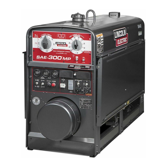
SAE-300 ® TABLE OF CONTENTS Page Installation..........................Section A Technical Specifications........................A-1 General Description........................A-2 Design Features ..........................A-2 Pre-Operation Installation......................A-3 Safety Precautions........................A-3 Exhaust Spark Arrester......................A-3 Location/Ventilation........................A-3 Angle of Operation........................A-4 Machine Grounding........................A-4 Lift Bail ............................A-4 Trailer ............................A-4 Vehicle Mounting........................A-5 Polarity Control and Cable Sizes ....................A-5 Pre-Operation Service ........................A-5 Oil, Fuel ............................A-5 Cooling System ..........................A-5... - Page 8 SAE-300 ® INSTALLATION TECHNICAL SPECIFICATIONS - SAE-300 ® INPUT - DIESEL ENGINE Make/Model Description Speed (RPM) Displacement Starting System Capacities 3 Cylinder 91.47 cu. in 12VDC battery Fuel: 16 gal. 24.7 HP(18.4kW) (1.5 ltrs) (Group 24, 650 60.6 L. PERKINS TURBO High Idle 1800 cold crank amps)
-
Page 9: Installation
SAE-300 ® INSTALLATION GENERAL DESCRIPTION ® The SAE-300 MP is a heavy duty, engine driven, DC arc weld- All Copper Windings - For long life and dependable operation. ing power source, capable of providing constant current output Engine Idler - The SAE-300 ®... -
Page 10: Pre-Operation Installation
SAE-300 ® INSTALLATION WARNING Welder Enclosure - The complete welder is rubber mounted on a rugged steel “C” channel base. Do not attempt to use this equipment until you have thoroughly The output terminals are placed at the side of the machines so read the engine manufacturer’s manual supplied with your that they are protected by the door. -
Page 11: Angle Of Operation
SAE-300 ® INSTALLATION ANGLE OF OPERATION WARNING Engines are designed to run in the level condition which is where the optimum performance is achieved. The maximum angle of continuous operation is 25º degrees in all directions, 35º intermittent (less than 10 minutes continuous) in all directions. •... -
Page 12: Vehicle Mounting
SAE-300 ® INSTALLATION PRE-OPERATION SERVICE WARNING VEHICLE MOUNTING CAUTION READ the engine operating and maintenance Improperly mounted concentrated loads may cause unstable instructions supplied with this machine. vehicle handling and tires or other components to fail. WARNING • Only transport this Equipment on serviceable vehicles which are rated and designed for such loads. -
Page 13: Battery Charging
SAE-300 ® INSTALLATION WARNING GASES FROM BATTERY can explode. • Keep sparks, flame and cigarettes away. BATTERY ACID can burn eyes and skin. • Wear gloves and eye protection and be careful when boosting, charging or work- ing near battery. To prevent EXPLOSION when: a) Installing a new battery - disconnect thenegative cable from the old battery first... -
Page 14: Electrical Device Use With This Product
DO NOT USE THESE DEVICES WITH THIS PRODUCT. The Lincoln Electric Company is not responsible for any damage to electrical components improperly connected to this product. -
Page 15: Engine Operation
SAE-300 ® OPERATION ENGINE OPERATION WARNING Allow the engine to run at high idle speed for several min- utes to warm the engine. Stop the engine and recheck the Do not attempt to use this equipment until you oil level, after allowing sufficient time for the oil to drain have thoroughly read the engine manufacturer’s into the pan. -
Page 16: Engine Break-In
OPERATION ENGINE BREAK-IN WELDER OPERATION WARNING Lincoln Electric selects high quality, heavy-duty industrial engines for the portable welding machines we offer. While it is ELECTRIC SHOCK can kill. normal to see a small amount of crankcase oil consumption dur- • Do not touch electrically live parts or... -
Page 17: How To Set Controls For Stick Welding
SAE-300 ® OPERATION HOW TO SET CONTROLS FOR STICK WELDING K857-1 and K2627-2 Remote Control unit can also 1. Set the Right Dial (Fine Current and OCV) to 70. be used as the Right Dial (Fine Current and OCV or wire voltage). -
Page 18: Gas-Shielding Flux-Cored Welding
SAE-300 ® OPERATION GAS-SHIELDED FLUX-CORED WELDING a. When welding or drawing power for lights or tools (approxi- Start by setting the Wire (CV) / Stick (CC) toggle switch to the Wire (CV) mately 100 watts minimum) from the receptacles, the idler position. -
Page 19: Accessories
The use of an arc welder for pipe thawing is not approved by the CSA, nor is it recommended or supported by Lincoln Electric. FIELD INSTALLED OPTIONAL ACCESSORIES Follow these steps: 1. -
Page 20: Maintenance
SAFETY PRECAUTIONS SAE-300 ® MAINTENANCE WARNING COOLING SYSTEM The SAE-300 ® MP is equipped with a pressure radiator. Keep Have qualified personnel do the maintenance work. Turn the radiator cap tight to prevent loss of coolant. Clean and flush the engine off before working inside the machine. In some the cooling system periodically to prevent clogging the passage and overheating the engine. -
Page 21: Nameplates
SAE-300 ® MAINTENANCE Replace brushes when they wear within 1/4” of the pigtail. A complete set of replacement brushes should be kept on hand. Lincoln brushes have a curved face to fit the commutator. Have an experienced maintenance person seat these brushes by lightly stoning the commutator as the armature rotates at full speed until contact is made across the full face of the brushes. -
Page 22: Engine Service
SAE-300 ® MAINTENANCE... -
Page 23: Gfci Testing And Resetting Procedure
SAE-300 ® MAINTENANCE GFCI TESTING AND RESETTING PROCEDURE The GFCI should be properly tested at least once every month or whenever it is tripped. To properly test and reset the GFCI: • If the GFCI has tripped, first carefully remove any load and check it for damage. -
Page 24: Troubleshooting
HOW TO USE TROUBLESHOOTING GUIDE WARNING Service and Repair should only be performed by Lincoln Electric Factory Trained Personnel. Unauthorized repairs performed on this equipment may result in danger to the technician and machine operator and will invalidate your factory warranty. - Page 25 SAE-300 ® TROUBLE SHOOTING Observe all Safety Guidelines detailed throughout this manual PROBLEMS POSSIBLE RECOMMENDED (SYMPTOMS) CAUSE COURSE OF ACTION Machine fails to hold the output Rough or dirty commutator. (heat) consistently. Brushes may be worn down to Limit. Field circuit may have variable resistance connection or inter- If all recommended possible areas of mittent open circuit due to...
- Page 26 SAE-300 ® TROUBLE SHOOTING Observe all Safety Guidelines detailed throughout this manual PROBLEMS POSSIBLE RECOMMENDED (SYMPTOMS) CAUSE COURSE OF ACTION Welder starts but fails to generate Generator or exciter brushes current. may be loose or missing. Exciter may not be operating. If all recommended possible areas of Field circuit of generator or misadjustment have been checked...
-
Page 27: Electronic Idler Troubleshooting Guide
ELECTRONIC IDLER TROUBLESHOOTING GUIDE SAE-300 ® TROUBLE SHOOTING With Idler Control Switch in the Auto Position, Engine Will Not Return to Low Idle in Approximately 15 Seconds After Welding and Auxiliary Loads are Removed Set Idler Control Switch to the Auto Position Check for Continuity through Idler Control Switch Open... - Page 28 ELECTRONIC IDLER TROUBLESHOOTING GUIDE SAE-300 ® TROUBLE SHOOTING With Idler Control Switch in the AUTO Position, Engine Will Not Pick Up Speed When: The Arc is Struck Both Auxiliary Load 1. Check Idler circuit wiring. Possible 1. Load too small. Try load Check for loose or disconnected Problems are wires from Current Sensing above 100 Watts.
- Page 29 SAE-300 ® TROUBLE SHOOTING Observe all Safety Guidelines detailed throughout this manual PROBLEMS POSSIBLE RECOMMENDED (SYMPTOMS) CAUSE COURSE OF ACTION Engine does not start. Lack of fuel. Air mixed in the fuel system. Clogged fuel filter. Irregular and faulty fuel supply (Injector pump trouble).
- Page 30 SAE-300 ® TROUBLE SHOOTING Observe all Safety Guidelines detailed throughout this manual * Count number of off pulses. CAUTION If for any reason you do not understand the test procedures or are unable to perform the tests/repairs safely, contact your Local Lincoln Authorized Field Service Facility for technical troubleshooting assistance before you proceed.
- Page 31 SAE-300 ® TROUBLE SHOOTING Observe all Safety Guidelines detailed throughout this manual PROBLEMS POSSIBLE RECOMMENDED (SYMPTOMS) CAUSE COURSE OF ACTION White or Blue Smoke. Excess engine oil. Too low viscosity of the engine oil. Faulty injection timing. Dark Grey Smoke. Unsuitable fuel.
-
Page 32: Diagnostic Led Flash Codes
SAE-300 ® TROUBLE SHOOTING Diagnostic LED Flash Codes(LED tied in harness at control board) Long Short Description Flash Flash Field coil shorted- fault can only be reset by restarting welder Welder output short circuit or overload, fault resets by restarting welder Negative armature in cvmode code VArm>90V in cvmode code after CR2enable Control board 18V Supply is under 16.2V... -
Page 33: Diagrams
SAE-300 ® DIAGRAMS WHITE... - Page 34 SAE-300 ® DIAGRAMS...
- Page 35 SAE-300 ® NOTES...
- Page 36 Lincoln Electric for advice or information about their use of our products. We respond to our customers based on the best information in our possession at that time. Lincoln Electric is not in a position to warrant or guarantee such advice, and assumes no liability, with respect to such information or advice.