Table of Contents
Advertisement
Operator's Manual
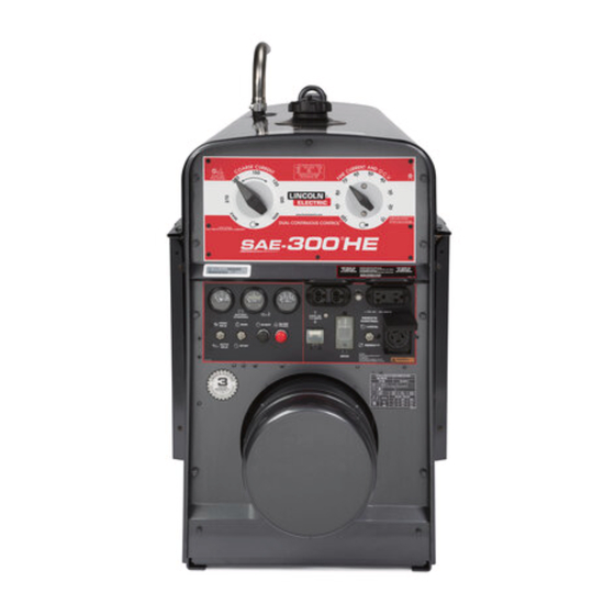
SAE-300
Register your machine:
www.lincolnelectric.com/register
Authorized Service and Distributor Locator:
www.lincolnelectric.com/locator
Save for future reference
Date Purchased
Code: (ex: 10859)
Serial: (ex: U1060512345)
IM10154-A
| Issue Date Jan- 14
© Lincoln Global, Inc. All Rights Reserved.
®
HE
For use with machines having Code Numbers:
11906, 12162
Need Help? Call 1.888.935.3877
to talk to a Service Representative
Hours of Operation:
8:00 AM to 6:00 PM (ET) Mon. thru Fri.
After hours?
Use "Ask the Experts" at lincolnelectric.com
A Lincoln Service Representative will contact you
no later than the following business day.
For Service outside the USA:
Email: globalservice@lincolnelectric.com
Advertisement
Table of Contents
Troubleshooting

Related Manuals for Lincoln Electric SAE-300 HE


Summary of Contents for Lincoln Electric SAE-300 HE
- Page 1 Operator’s Manual ® SAE-300 For use with machines having Code Numbers: 11906, 12162 Need Help? Call 1.888.935.3877 Register your machine: to talk to a Service Representative www.lincolnelectric.com/register Authorized Service and Distributor Locator: Hours of Operation: www.lincolnelectric.com/locator 8:00 AM to 6:00 PM (ET) Mon. thru Fri. Save for future reference After hours? Use “Ask the Experts”...
- Page 2 THANK YOU FOR SELECTING KeeP your head out oF the Fumes. A QUALITY PRODUCT BY DON’T get too close to the arc. Use LINCOLN ELECTRIC. corrective lenses if necessary to stay a reasonable distance away from the arc. READ and obey the Material Safety...
-
Page 3: California Proposition 65 Warnings
American Welding Society, P.O. Box 351040, Miami, Florida 33135 or ELECTRIC AND CSA Standard W117.2-1974. A Free copy of “Arc Welding Safety” MAGNETIC FIELDS MAY booklet E205 is available from the Lincoln Electric Company, 22801 St. Clair Avenue, Cleveland, Ohio 44117-1199. BE DANGEROUS BE SURE THAT ALL INSTALLATION, OPERATION, 2.a. -
Page 4: Electric Shock Can Kill
S FETY ELECTRIC SHOCK ARC RAYS CAN BURN. CAN KILL. 3.a. The electrode and work (or ground) circuits are 4.a. Use a shield with the proper filter and cover plates to protect your electrically “hot” when the welder is on. Do eyes from sparks and the rays of the arc when welding or not touch these “hot”... - Page 5 S FETY WELDING AND CUTTING CYLINDER MAY EXPLODE IF SPARKS CAN CAUSE DAMAGED. FIRE OR EXPLOSION. 7.a. Use only compressed gas cylinders containing the correct shielding gas for the process used 6.a. Remove fire hazards from the welding area. If and properly operating regulators designed for this is not possible, cover them to prevent the the gas and pressure used.
- Page 6 S FETY PRÉCAUTIONS DE SÛRETÉ 6. Eloigner les matériaux inflammables ou les recouvrir afin de prévenir tout risque d’incendie dû aux étincelles. Pour votre propre protection lire et observer toutes les instructions et les précautions de sûreté specifiques qui parraissent dans ce 7.
-
Page 7: Table Of Contents
TABLE OF CONTENTS Page ________________________________________________________________________ Installation .......................Section A Technical Specifications ..................A-1 General Description ....................A-2 Design Features ....................A-2 Pre-Operation Installation ..................A-3 Safety Precautions ..................A-3 Exhaust Spark Arrester ...................A-3 Location/Ventilation..................A-3 Angle of Operation ..................A-4 Machine Grounding..................A-4 Lift Bail ......................A-4 Trailers ......................A-4 Vehicle Mounting.....................A-5 Polarity Control and Cable Sizes ..............A-5 Pre-Operation Service ...................A-5 Oil, Fuel......................A-5... -
Page 8: Installation
INSTALLATION TECHNICAL SPECIFICATIONS - SAE-300 ® INPUT - DIESEL ENGINE Make/Model Description Speed (RPM) Displacement Starting System Capacities 3 Cylinder 91.47 cu. in 12VDC battery Fuel: 16 gal. 24.8 HP(18.5kW) (1.5 ltrs) (Group 24, 650 60.6 L. KUBOTA Naturally Aspirated High Idle 1800 cold crank amps) D1503-M Water-Cooled... -
Page 9: General Description
INSTALLATION GENERAL DESCRIPTION All Copper Windings - For long life and dependable operation. ® The SAE-300 HE is a heavy duty, engine driven, DC ® Engine Idler - The SAE-300 HE is equipped with an arc welding power source, capable of providing con- electronic automatic engine idler. -
Page 10: Pre-Operation Installation
INSTALLATION PRE-OPERATION INSTALLATION Welder Enclosure - The complete welder is rubber mounted on a rugged steel “C” channel base. WARNING The output terminals are placed at the side of the Do not attempt to use this equipment until you machines so that they are protected by the door. The have thoroughly read the engine manufacturer’s manual supplied with your welder. -
Page 11: Angle Of Operation
INSTALLATION ANGLE OF OPERATION LIFT BAIL A lift bail is provided for lifting with a hoist. Engines are designed to run in the level condition which is where the optimum performance is achieved. The maximum angle of continuous operation is 20º WARNING degrees in all directions, 30º... -
Page 12: Vehicle Mounting
INSTALLATION VEHICLE MOUNTING PRE-OPERATION SERVICE WARNING CAUTION Improperly mounted concentrated loads may READ the engine operating and maintenance cause unstable vehicle handling and tires or other instructions supplied with this machine. components to fail. ------------------------------------------------------------------------ • Only transport this Equipment on serviceable vehicles which are rated and designed for such WARNING loads. -
Page 13: Battery Charging
INSTALLATION BATTERY CHARGING WARNING GASES FROM BATTERY can explode. • Keep sparks, flame and cigarettes away. BATTERY ACID can burn eyes and skin. • Wear gloves and eye protection and be careful when boosting, charging or working near battery. To prevent ExPLOSION when: a) Installing a new battery - disconnect thenega- tive cable from the old battery first and connect the negative cable to the new battery last. -
Page 14: Electrical Devices Use With This Product
DO NOT USE THESE DEVICES WITH THIS PRODUCT. The Lincoln Electric Company is not responsible for any damage to electrical components improperly connected to this product. ® SAE-300... -
Page 15: Operation
OPERATION ENGINE OPERATION Allow the engine to run at high idle speed for sev- eral minutes to warm the engine. Stop the engine WARNING and recheck the oil level, after allowing sufficient time for the oil to drain into the pan. If the level is Do not attempt to use this equipment until you down, fill it to the full mark again. -
Page 16: Engine Break-In
OPERATION ENGINE BREAK-IN WELDER OPERATION WARNING Lincoln Electric selects high quality, heavy-duty indus- trial engines for the portable welding machines we ELECTRIC SHOCK can kill. offer. While it is normal to see a small amount of • Do not touch electrically live parts or crankcase oil consumption during initial operation, electrode with skin or wet clothing. -
Page 17: How To Set Controls For Stick Welding
OPERATION HOW TO SET CONTROLS FOR STICK K924-4 WELDING Remote Control unit can also be used as the Right Dial (Fine 1. Set the Right Dial (Fine Current and OCV) to 60. Control and OCV). STICK / TIG WELDING Start by setting the right-side Fine Current and OCV control dial to 60, then set the left-side Coarse Current control dial to the desired current using the dial markings as an approxi- mate guideline. - Page 18 OPERATION GAS-SHIELDED FLUx-CORED WELDING 2. In the “Auto” position, the idler oper- (WITH A K3964-1 WIRE FEED MODULE INSTALLED) ates as follows: Start by setting the Wire (CV) / Stick (CC) toggle switch to the Wire (CV) position. Then set the left-side Coarse a.
-
Page 19: Accessories
The use of an arc welder for pipe thawing is not approved by the CSA, nor is it recommended or supported by Lincoln Electric. ------------------------------------------------------------------------ FIELD INSTALLED OPTIONAL ACCESSORIES Follow these steps: 1. -
Page 20: Maintenance
MAINTENANCE SAFETY PRECAUTIONS COOLING SYSTEM WARNING ® The SAE-300 HE is equipped with a pressure radia- tor. Keep the radiator cap tight to prevent loss of Have qualified personnel do the maintenance coolant. Clean and flush the cooling system periodi- work. -
Page 21: Idler Maintenance
MAINTENANCE Replace brushes when they wear within 1/4” of the pigtail. A complete set of replacement brushes should be kept on hand. Lincoln brushes have a curved face to fit the commutator. Have an experienced mainte- nance person seat these brushes by lightly stoning the commutator as the armature rotates at full speed until contact is made across the full face of the brush- es. -
Page 22: Engine Service Chart
MAINTENANCE ENGINE SERVICE EVERY DAY OR EVERY 8 HOURS FIRST SERVICE (50 HOURS) EVERY 100 HOURS OR 3 MONTHS EVERY 150 HOURS OR 4 MONTHS EVERY 200 HOURS OR 9 MONTHS EVERY 400 HOURS OR 12 MONTHS EVERY 500 HOURS OR 15 MONTHS EVERY 800 HOURS OR 24 MONTHS ENGINE SERVICE (NOTE 2) MAINTENANCE ITEM... -
Page 23: Gfci Testing And Resetting Procedure
MAINTENANCE GFCI TESTING RESETTING PROCEDURE The GFCI should be properly tested at least once every month or whenever it is tripped. To properly test and reset the GFCI: • If the GFCI has tripped, first carefully remove any load and check it for damage. •... -
Page 24: Troubleshooting
HOW TO USE TROUBLESHOOTING GUIDE WARNING Service and Repair should only be performed by Lincoln Electric Factory Trained Personnel. Unauthorized repairs performed on this equipment may result in danger to the technician and machine operator and will invalidate your factory warranty. For your safety and to avoid Electrical Shock, please observe all safety notes and precautions detailed throughout this manual. - Page 25 TROUBLESHOOTING Observe all Safety Guidelines detailed throughout this manual PROBLEMS POSSIBLE RECOMMENDED (SYMPTOMS) CAUSE COURSE OF ACTION Machine fails to hold the output Rough or dirty commutator. (heat) consistently. Brushes may be worn down to Limit. Field circuit may have variable resistance connection or inter- If all recommended possible areas of mittent open circuit due to...
- Page 26 TROUBLESHOOTING Observe all Safety Guidelines detailed throughout this manual PROBLEMS POSSIBLE AREAS OF RECOMMENDED (SYMPTOMS) MISADJUSTMENTS(S) COURSE OF ACTION Welder starts but fails to generate Generator or exciter brushes current. may be loose or missing. Exciter may not be operating. Field circuit of generator or exciter may be open.
-
Page 27: Electronic Idler Troubleshooting Guide
TROUBLESHOOTING ELECTRONIC IDLER TROUBLESHOOTING GUIDE With Idler Control Switch in the Auto Position, Engine Will Not Return to Low Idle in Approximately 15 Seconds After Welding and Auxiliary Loads are Removed Set Idler Control Switch to the Auto Position Check for Continuity through Idler Control Switch Open Closed... - Page 28 TROUBLESHOOTING ELECTRONIC IDLER TROUBLESHOOTING GUIDE With Idler Control Switch in the AUTO Position, Engine Will Not Pick Up Speed When: The Arc is Struck Both Auxiliary Load 1. Check Idler circuit wiring. Possible 1. Load too small. Try load Check for loose or disconnected Problems are wires from Current Sensing above 100 Watts.
- Page 29 TROUBLESHOOTING Observe all Safety Guidelines detailed throughout this manual PROBLEMS POSSIBLE RECOMMENDED (SYMPTOMS) CAUSE COURSE OF ACTION Engine does not start. Lack of fuel. Air mixed in the fuel system. Clogged fuel filter. Irregular and faulty fuel supply (Injector pump trouble). Glow plug not heated.
- Page 30 TROUBLESHOOTING LIGHT CODE FAILURE DETECTED POSSIBLE CAUSE - CORRECTIVE MEASURE LONG 1, SHORT 1 RPM IS OVER 115% OF RATED RPM (2070 RPM) ACTUATOR IS STUCK - REMOVE ACTUATOR AND VERIFY PLUNGER PULLS IN WHEN ENERGIZED LONG 1, SHORT 2 LOW OIL PRESSURE DETECTED FOR 1 SECOND LOW OIL - CHECK OIL LEVEL ON DIPSTICK FAULTY OIL PRESSURE SWITCH - CHECK THAT "WK"...
- Page 31 TROUBLESHOOTING Observe all Safety Guidelines detailed throughout this manual PROBLEMS POSSIBLE RECOMMENDED (SYMPTOMS) CAUSE COURSE OF ACTION White or Blue Smoke. Excess engine oil. Too low viscosity of the engine oil. Faulty injection timing. Dark Grey Smoke. Unsuitable fuel. Excess injection. Faulty function of the engine.
-
Page 32: Diagrams
DIAGRAMS WHITE ® SAE-300... - Page 33 DIAGRAMS ® SAE-300...
- Page 34 NOTES SAE-300 ®...
- Page 35 Lincoln Electric for advice or information about their use of our products. We respond to our customers based on the best information in our possession at that time. Lincoln Electric is not in a position to warrant or guarantee such advice, and assumes no liability, with respect to such information or advice.