Robertshaw 300-224 Installation And Programming Instructions
Deluxe programmable thermostats
Hide thumbs
Also See for 300-224:
- Installation and programming instructions (40 pages) ,
- Installation & programming manual (10 pages) ,
- Specifications (2 pages)
Table of Contents
Advertisement
Advertisement
Table of Contents

Related Manuals for Robertshaw 300-224


Summary of Contents for Robertshaw 300-224
- Page 1 Installation and Programming Instructions for Deluxe Programmable Thermostats...
-
Page 2: Table Of Contents
TABLE OF CONTENTS INTRODUCTION ..............STANDARD FEATURES ............THERMOSTAT LOCATION ..........REMOVING THE THERMOSTAT FROM THE SUBBASE ..DESCRIPTION OF THE DIP SWITCH FUNCTIONS ....9-11 COVER LOCK ..............REPLACING THE THERMOSTAT ON THE SUBBASE ....WIRING DIAGRAMS ............13-24 PROGRAMMING 7 DAY MODELS ........ - Page 3 POWER FAILURES ................29 OUTDOOR TEMPERATURE INDICATOR (OPTIONAL) ......29 PROGRAMMING 5/2 DAY MODELS ..........30-34 TYPICAL RESIDENTIAL SCHEDULE ..........30 PLANNING YOUR SCHEDULE ............31 SETTING THE CURRENT DAY AND TIME ........... 32 SETTING THE VVEEKDAY PROGRAM TIMES AND HEATING TEMPERATURES ..32-33 SETTING THE VVEEKEND PROGRAM TIMES AND HEATING TEMPERATURES.
-
Page 4: Introduction
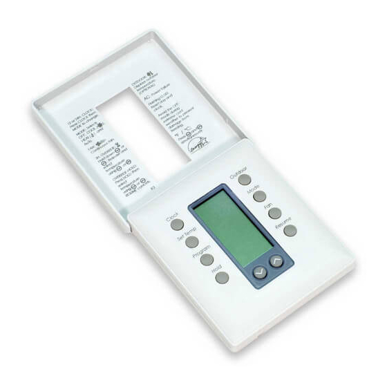
INTRODUCTION The Deluxe Programmable Thermostat represents the mast advanced solid-state, microcomput- er temperature control an the market today. The thermostat incorporates state-of-the-art tech- nology packaged in an extremely low profile designer series case. Ultra-Touch controls are com- bined with an easy-to-read, full function liquid crystal display to provide the ultimate in user friendly operation of your heating and air conditioning equipment. - Page 5 FOR MODELS 300-224, 226, 230 Press to settle display the Press ED real time day. outdoor temperah.lre hour and minute (optional) Press to change from select Press ED Standard Time to heat/cod/auto/off. Daylight Saving Time The word is displayed for 5 sernnds.
- Page 6 FOR MODELS 300-225, 227, 229 Press to display the oL,tdoorternperetLlre (Optional} select Press heat/0 urb/off. The word is displayed or 5 seconds. (Emergency heat For 300-227) Select for contirkUOLIS r,n or auto r Press to hold Hie current setting. The p rogr-a m will hold indefinitely or irritil PrESSo the hold...
-
Page 7: Thermostat Location
THERMOSTAT LOCATION To ensure proper operation, the thermostat should be mounted on an inside wall in a frequently occupied area of the building. In addition, its position must be at least 18" (46 cm) from any out- side wall, and approximately 5, (1.5 m) above the floor in a location with freely circulating air of an average temperature. -
Page 8: Removing The Thermostat From The Subbase
REMOVING THE THERMOSTAT FROM THE SUBBASE 1. Insert a flat blade screwdriver or ooin 1/8" into the slot located in the bottom center of the thermostat case and twist 1/4 turn. lai s eeri you feel or hear a click, grasp thdesep_ ners an the bottom two from... -
Page 9: Description Of The Dip Switch Functions
2 Minute or 4 Minute Minimum On Times Keypad Lock Place the switch in the locked position to lockout all buttons except the OUTDOOR button. (300-224, 300-225, 300-229) Plenum Fan Switch OFF - Fan comes on immediately with heat (used on electric heat). - Page 10 (300-227, 300-229) Single or Multistate for 300-227 or 1 heat/1 cool for For equipment with a single compressor (2 heat/1 cool 300- 229}, switch to single stage. For equipment with two compressors (3 heat/2 cool for 330-227 or 2 heat/2 cool for 300-229), switch to multistage. (300-226, 300-227, 300-229) LED #1 Switch ON will energize the LED light pipe at the top of the thermostat plus the filter indicator on...
- Page 11 (3O0-226, 300-227) Setting the Outdoor High and Low Temperature Balance Points When using the optional Robertshaw remote outdoor sensor (Uni-Line #10-5291, you can select the outdoor balance points to lock-out the auxiliary heat and/or the compressor of the heat pump.
-
Page 12: Cover Lock
COVER LOCK You also may lock the cover down to prevent unauthorized access to the thermostat by adding the dear plastic lock (included in the installation bag). To install, remove the thermostat from the subbase and place the dear plastic lock in the subbase as shown below. Replace the thermo- stat and close the cover. - Page 14 OUTPUT TERMINAL FUNCTIONS - 300-224 24VAC supply from heating ....Energizes the heating equipment with a call mn inr0,111 k 7 ma Mtial for heating RC ..... 24VAC supply from cooling ....Energizes the cooling equipment with a call 300-224...
-
Page 15: Wiring Diagrams
WIRING DIAGRAM - Note 1: If jumper removed, a sep- arate transformer must be used to power the loads. Note 2 This thermostat may be used with 24 Volt DC. The nega- ev Ms 4 everts tive side of the DC supply must be Small Fan 4 rein ;c4-.1:1:. - Page 16 OUTPUT TERMINAL FUNCTIONS - 300-225 Energizes on a call for first stage heat W1 ..Y1 ..Energizes with a call for coaling G ..Fan is energized with a call for heating or selected by pressing the FAN button ..
- Page 18 OUTPUT TERMINAL FUNCTIONS - 300-226 .Auxiliary heat is energized second stage heating or emergency heat Y1 . Compressor is energized with a call for heating or cooling ....Fan is energized with a call for heating or cooling or selected by pressing the FAN IADW arm.
- Page 20 OUTPUT TERMINAL FUNCTIONS - 300-227 W2 .... Energizes aisriliary heat as second stage emergency heat Y2... .Energizes compressor it2 call for second On a Stage heating Or COOHRO .Energizes auxiliary heat as last stage heating or first W1 ..stage emergency heat .Energizes compressor #1 on call...
-
Page 21: Wiring Diagram
WIRING DIAGRAM - Note 1: If jumper is removed, a separate transformer must be used to power the bads. Note This thermostat may be used with 24 Volt DC. The negative side of the DC supply must be wired to the 24V(C) terminal. .7ral If- cc v-7 AL, n... - Page 22 OUTPUT TERMINAL FUNCTIONS - 300-229 W2... Energizes auxiliary heat as second stage emer- gency heat Y2..„.. Energizes compressor r2 on a call for second stage heating or cooling L4424 L-nt1[4.3 fli Energizes auxiliary heat as last stage heating or first stage emergency heat ..
- Page 23 WIRING DIAGRAM - -nr.ule :91 n L•:• ktyaed pe [11i:clod Iner...
- Page 24 OUTPUT TERMINAL FUNCTIONS - 300-230 RC ..24VAC supply from coaling equipment transformer .... Energizes the cooling equipment with u'nrlo u rkSa 2 'y"pa undulock .nuscl " a call for coaling .... Fan is energized with a call for cooling of selected by pressing the FAN but- 300-230 f.•...
-
Page 25: Planning Your Schedule
PLANNING YOUR SCHEDULE (300-225, 300-227, 300-229) Your new Robertshaw programmable thermostat has been designed so that you can select either 2 program periods (Day and Night) or 4 program periods (Morning. Day, Evening and Night). The thermostat comes from the factory set for 4 program periods. To change this setting. -
Page 27: Setting Your Program Times
SETTING YOUR PROGRAM TIMES Referring to your Schedule Planner, you now will enter the times for the program periods. Press the PROGRAM button. The display will flash a day of the week. Press the s or v_ buttons to select the day you wish to program. We suggest starting with Monday.) Press the PROGRAM button. -
Page 28: Temperature Override
TEMPERATURE OVERRIDE Temporary Override (3 hours) You may change the temperature setting temporarily at any time without affect- ing the program. Press the a or t buttons. The current event temperature and made of operation will be displayed. Press the a or t buttons again to adjust the temperature. This temperature will be maintained for three hours. -
Page 29: Changing Fahrenheit (F) To Celsius ('C)
MODE button. The display will change automatically. POWER FAILURES This Robertshaw thermostat will maintain the program settings during any type of power failure. If power fails, AC will be displayed for 30 minutes. After 30 minutes, the display will go blank. If power is restored within the first 30 minutes, the thermostat will resume normal operation. -
Page 30: Programming 5/2 Day Models
TYPICAL RESIDENTIAL SCHEDULE (300-224, 300-226, 300-230) Weekday Time Weekend Time Temperature Settings AM/PM AM/PM HEAT MORNING 6:00 AM 8:00 AM s 61. COOL HEAT 9:00 AM 8:00 AM COOL HEAT EVENING /- ' 3:30 PM 8:00 AM COOL HEAT NIGHT... -
Page 31: Planning Your Schedule
PLANNING YOUR SCHEDULE (300-224, 300-226, 300-230) To help save programming time, we suggest you use the worksheet below to set your specific program. We suggest you set your desired program times approximately 1 hour before the time required to reach the set temperature. Therefore, if you get up at 7:00 AM, set the morning temperature to come on at 6:00 AM. -
Page 32: Setting The Current Day And Time
SETTING THE CURRENT DAY AND TIME Before you set the current day and time, set the thermostat into the proper time mode by press- ing the Daylight Saving Time (DST} button. If the thermostat has been installed during Daylight ing Time, press and release the DST button until the clock symbol in the lower right corner of the display appears. -
Page 33: Setting The Vveekend Program Times And Heating - Temperatures
5. Press the s or t button to adjust the minutes. (Note the minutes are in increments of 10.) 6. Press the PROGRAM button. The heating temperature will be displayed. 7. Press the s or t button to adjust to the desired heating temperature. a Repeat Steps 2 -7 for the Day, Evening, and Night program periods. - Page 34 (Example: If you set the cooling temperature less than two degrees above the heating temperature, the thermostat will automatically maintain a two degree separation between heating and cooling by lowering the heating temperature. 4. Press the s or t button to adjust to the desired cooling temperature. rdc Tu DI FT 5.
-
Page 35: Reviewing Scheduled Times And Temperatures
REVIEWING SCHEDULED TIMES AND TEMPERATURES To review your programmed schedules, repeatedly press and release the PROGRAM button. Each scheduled event will be displayed starting with the weekday start times and temperatures and ending with the weekend start times and temperatures. To cancel your review, simply press and release the RESUME button or wait 15 seconds for the thermostat to resume automatically. -
Page 37: Specifications
SPECIFICATIONS (300-225, 300-226, 300-227, 300-229) Rated Voltage ........20-30 VAC, 24 nominal Rated A.C................050 Amps to 0.75 Amps continuous Current per output with surges to 3 Amps Max. Rated D.C................. 0 Amps to 0.75 Amps continuous Current per output with surges to 3 Amps Max. -
Page 38: Important Installer's Note
IMPORTANT INSTALLER'S NOTE FOR THE 300-224 This thermostat is equipped with a transformer wiring fault indicator (located along the top left side of the thermostat). If the red light is ON when the wiring is complete, you must check the equipment to ensure that the transformers are wired in accordance with the diagrams provided on this sheet. - Page 39 TWO TRANSFORMER SYSTEM If the fault indic.ator is ON the transformers are out of phase. Switch the secondary wires of one of the transformers (NOT BOTHy and ensure the red light goes OFF. Separate RH and RC Wires Equipm0r11. TratISIO.N3r8...
- Page 40 UNI-LINE NORTH AMERICA ROBERTSHAW CONTROLS COMPANY • UNI-LINE NORTH AMERICA • PO. BOX 2000 • CORONA. CA 92E179-1736 ©2000 Printed In U.S.A. 4/00 1-898...