Avaya G450 Quick Start Manual
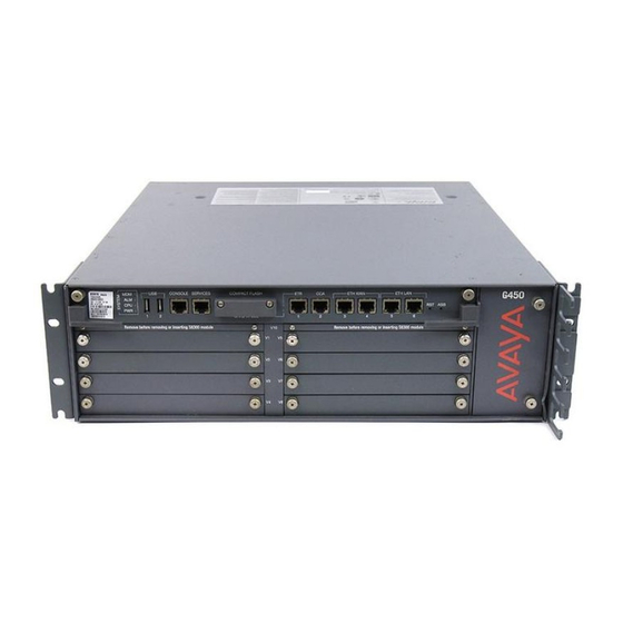
Media gateway
Hide thumbs
Also See for G450:
- Cli reference manual (1334 pages) ,
- Manual (736 pages) ,
- Installing and upgrading (324 pages)

Related Manuals for Avaya G450


Summary of Contents for Avaya G450
- Page 1 Quick Start for Hardware Installation: Avaya G450 Media Gateway 03-602053 Issue 2 December 2008...
- Page 2 Avaya support Avaya provides a telephone number for you to use to report problems or to ask questions about your product. The support telephone number is 1-800-242-2121 in the United States. For additional support telephone...
-
Page 3: Chapter 1: Before You Start
Avaya Support Web site, at http://support.avaya.com. Preparing the G450 Serial Number In order to create the license file, you need the serial number of the G450. The serial number is printed on a sticker on the back of the G450 chassis. -
Page 4: Downloading A G450 License File To Your Laptop
The INADS IP address is required in order to configure the S8300’s modem for alarming. If you are preparing a G450 with an S8300 for a remote installation, you must first obtain an INADS IP address. Use the Automatic Registration Tool (ART) to obtain an IP address for an INADS alarming modem. -
Page 5: Preparing Needed Hardware
Minimum of four wood screws ● Minimum of four screws (pan head at least ½ in, # 10-12 screw) to fasten the G450 to the wall ● You might also need wire cutters to attach the grounding conductors, if your site uses a ground block. - Page 6 Before you Start Relative humidity – 10-90% relative humidity ● Minimum clearance for ventilation – 18 in. (45 cm) ● Weight support – 22.5-35 lbs (10-16 kg) ● 6 Quick Start for Hardware Installation: Avaya G450 Media Gateway...
-
Page 7: Chapter 2: Unpack The Device
For ease of installation, it is recommended to remove the power supply unit(s) before unpacking the G450. 1. Open the package. Note that the G450 is lying flat. Turn it so that the rear panel is facing up. 2. Remove the power supply unit (PSU). If you ordered two power supplies, remove them both. - Page 8 One Cable Management Fifteen 3/8 in. Flat Head Screws Assembly brackets Two 5/16 in. Round Head Screw Two Serrated Lock Washers One Ground One Jumper for Screw Bridging NVRAM init Pins 8 Quick Start for Hardware Installation: Avaya G450 Media Gateway...
-
Page 9: Chapter 3: Mount The Device
Chapter 3: Mount the Device You can position the Avaya G450 Media Gateway on a suitable table, or mount it in a rack or on the wall. Once the G450 is mounted, re-insert the Power Supply Units. Positioning on a Table To install the Avaya G450 Media Gateway as a tabletop unit: 1. -
Page 10: Attaching Mounting Brackets
1. Position a bracket over the desired mounting position. 2. Affix the bracket to the chassis with five flat head 3/8 in. screws. 3. Tighten the screws with the screwdriver. 10 Quick Start for Hardware Installation: Avaya G450 Media Gateway... -
Page 11: Mounting The G450
2. Mark the plywood with the location of the G450 bracket screw holes before fastening the plywood to the wall. 3. Position the G450 so that its front panel is facing up, and secure it to the plywood using a minimum of four screws (pan head at least ½ in, # 10-12 screw). -
Page 12: Installing The Power Supply Units
Removing the Power Supply Units on page 7 ) . 1. Position the power supply unit before the opening at the rear of the G450 and engage both sides of the PSU in the interior guides. 2. Slide the PSU slowly into the chassis, maintaining an even pressure to assure that the PSU does not become twisted or disengaged from the guides. -
Page 13: Chapter 4: Install Media Modules
Chapter 4: Install Media Modules The required media modules may be pre-installed in the G450 chassis. If this is the case, skip this chapter. If the media modules are not pre-installed, or if you want to replace modules or add new media modules, install the necessary Media Modules and related components to support the configuration required for your site. - Page 14 V1 – V8 Provides eight ports for connecting up to eight ISDN trunks or 16 ISDN BRI stations. MM722 V1 – V8 Provides two ports for connecting ISDN trunks. S8300 Server 14 Quick Start for Hardware Installation: Avaya G450 Media Gateway...
-
Page 15: Installing An S8300 Server Module
Installing an S8300 Server Module The S8300 can only be inserted in slot V1 on the left side of the Avaya G450 Media Gateway. 1. If you are inserting an S8300/B or S8300/C module, remove the plate above slot V1, labelled “Remove before removing or inserting S8300 module”. - Page 16 Install Media Modules 16 Quick Start for Hardware Installation: Avaya G450 Media Gateway...
-
Page 17: Chapter 5: Install Media Resources And Psu
Adding or removing media resources You can add or remove media resources (VoIP) modules in the G450 main board. To do so, you must pull out the G450 main board. The G450 supports hot insertion and removal of the main board without power drop. -
Page 18: Adding Or Removing Media Resource Modules: Mp20 And Mp80
Adding or removing media resource modules: MP20 and MP80 The G450 main board has four slots for media resources. Each slot can accommodate either an MP20 (Media Processor 20) module or an MP80 (Media Processor 80) module. An MP20 provides 20 channels, and an MP80 provides 80 channels. -
Page 19: Inserting The G450 Main Board
Inserting the G450 main board 1. Open the latches on both sides of the slot. 2. Insert the G450 main board vertically into the slot. 3. Push the main board in until the latches begin to close. 4. Close and tighten the two captive screws on the front panel. -
Page 20: Inserting A Power Supply Unit
Install Media Resources and PSU Inserting a power supply unit The G450 provides full redundant, load sharing power supply units (1 + 1). A single power supply unit provides sufficient power for any G450 configuration. If you choose to install two power supply units, they operate in a load sharing mode. -
Page 21: Chapter 6: Power Up
Both safety grounds must be connected to an approved ground (see Chapter 2 of Installing and Upgrading the Avaya G450 Media Gateway, 03-602054, for the definition of an approved ground). If a power cord accompanies the G450, use that cord whenever possible. -
Page 22: Using A Ground Block
2. Connect the other end of the power cable into a mains socket. LED Sequence When you turn on the G450, the following LED sequence occurs: 1. The PWR LED on the front panel lights, indicating the operational status of the power supply unit... -
Page 23: Chapter 7: Prepare For Configuration
Preparing a G450 with an S8300 Server Use the Avaya Installation Wizard (IW) to configure the G450 with an S8300. If a remote technician is configuring the G450, see Preparing the G450 with an S8300 for a remote configuration on page 25. - Page 24 (IW) opening screen appears. Configuring the G450 and S8300 using the Avaya IW Step through the screens of the Avaya IW to configure the S8300 and the G450. Take note of the following items: 1. On the initial IW screen, you can upgrade the wizard if you have a more current version of the AIW.rpm wizard file.
- Page 25 25. On the Authentication File screen, load the CM authentication file that you prepared from your laptop. Preparing the G450 with an S8300 for a remote configuration If you need to prepare the G450 with an S8300 for a remote configuration, you must attach and enable a modem.
- Page 26 5. Double-click the GIW icon on the laptop to open the Gateway Installation Wizard. The Overview screen appears. 6. Click Continue. The COM Port Selection screen appears. 7. Select the COM port you are using on the laptop to connect to the G450 from the COM Port drop down list. Note: Not every COM port works with every laptop.
-
Page 27: Configuring The G450 Using The Giw
10. Click Finish to complete the G450 configuration. Preparing for a remote configuration of the G450 If you need to prepare the G450 for a remote configuration, you must attach a modem and enable it using the GIW. 1. From the Wizard Usage Options screen, select Enable the modem for remote installation, and click Continue. -
Page 28: Next Steps
Using the Command Line Interface For information about configuring the G450 with the Command Line Interface: For instructions on how to connect to the CLI, review Chapter 4 of Administration for the Avaya G450 ● Media Gateway, 03-602055 - Accessing the Avaya G450 Media Gateway.