Table of Contents
Advertisement
Installation
Instructions
"If you have questions, call 800-GE-CARES
www.GEAppliances.com"
Before you begin
Read these instructions carefully and completely
IMPORTANT
•
-Save these instructions for
local inspector's use.
IMPORTANT
•
-Observe all governing
codes and ordiances.
ATTENTION: INSTALLER
All electric wall ovens must be hard wired (direct wired) into an approved
junction box. A "plug and receptacle" is not permitted on these products.
Parts Included
4 screws (single)
8 screws (double)
Tools You Will Need
1/8" Drill Bit &
Electric or
Hand Drill
Pub. No. 31-10435
4053P417-1
229C
Bottom Trim
Phillips
Screwdriver
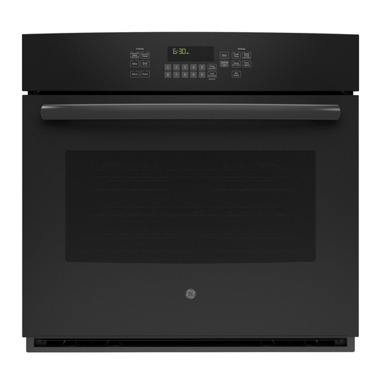
30" Built In Wall Oven
JTP15, JTP17, JTP18, JTP27, JTP45, JTP47, JTP56,
JT910, JT910WA, JT950AA, JT950, ZET737, ZET757
• Note to Installer- Be sure to leave these
instructions with the consumer.
• OWNER- Keep these instructions for future
reference.
• NOTE- This appliance must be properly
grounded.
Materials Needed
Strain Relief
Clamp
1
or visit our website at:
Wire Nuts
Junction
Box
36" of String
Advertisement
Table of Contents

Related Manuals for GEAppliances JTP15


Summary of Contents for GEAppliances JTP15
-
Page 1: Before You Begin
Installation 30” Built In Wall Oven JTP15, JTP17, JTP18, JTP27, JTP45, JTP47, JTP56, Instructions JT910, JT910WA, JT950AA, JT950, ZET737, ZET757 “If you have questions, call 800-GE-CARES or visit our website at: www.GEAppliances.com” Before you begin • Note to Installer- Be sure to leave these instructions with the consumer. -
Page 2: Important Safety Instructions
Installation Instructions IMPORTANT SAFETY INSTRUCTIONS Electrical For Your Safety Requirements • Be sure your oven is installed properly by a qualified installer or service technician. This appliance must be supplied with the • Be sure the oven is securely installed in a proper voltage and frequency, and connected cabinet that is firmly attached to the to an individual, properly grounded branch... -
Page 3: Pre-Installation Checklist
Installation Instructions Pre- Installation Checklist Open the door to the stop position. ALL INSTALLATION INFORMATION ON THE FOLLOWING PAGES ARE TO BE USED FOR SINGLE AND DOUBLE OVEN INSTALLATION! Remove packaging materials. Check behind hinges, and under false bottom. Remove labels on door, plastic on trims and panel, DO NOT LIFT THE DOOR BY THE and all tape around oven. - Page 4 Installation Instructions Pre- Installation Checklist cont. Place the oven on a table or Cover hinge with paper towel rolls platform even with the cutout or toweling. opening. (Platform must support 150 lbs. single, 275 lbs double.) Remove the bottom trim from the CAUTION: When the door is top of the oven.
- Page 5 Installation Instructions Cutouts for Single Built-In-Oven CUTOUT 5" WIDTH Cabinet Width 30” 28 1/2" MIN. 28 5/8" MAX. Recommended Cutout Location JUNCTION BOX LOCATION from Floor 32 1/2” ALLOW 11/16" FOR OVERLAP OF THE OVEN OVER SIDE Cutout Depth 23 1/2” Min. EDGES OF CUTOUT THE OPENING BETWEEN INSIDE...
- Page 6 Installation Instructions Cutouts for Double Built-In-Oven CUTOUT WIDTH 5" 28 1/2" MIN. 28 5/8" MAX. Cabinet Width 30” JUNCTION BOX Recommended LOCATION Cutout Location from Floor 12” ALLOW 11/16" FOR OVERLAP OF THE OVEN Cutout Depth 23 1/2” Min. OVER SIDE EDGES OF CUTOUT Cutout Wdth 28 1/2”...
- Page 7 Installation Instructions Cutouts For Single Oven Under Counter Gas or electric cooktops may be installed over this oven. See cooktop installation instructions for cutout size. Gas and electrical connections See label on top of oven for for 30" gas cooktop must be approved cooktop models.
-
Page 8: Electrical Connections
Installation Instructions Electrical Connections Turn off the circuit breaker or remove NEW CONSTRUCTION AND FOUR- fuses to the oven branch circuit. CONDUCTOR BRANCH CIRCUIT CONNECTION With the oven in front of the cabinet opening, on a table or platform, connect the flexible conduit to the electrical •... -
Page 9: Three-Conductor Branch Circuit Connection
Installation Instructions Electrical Connections cont. Do not shorten the flexible conduit.The THREE-CONDUCTOR BRANCH conduit strain Relief Clamp must be CIRCUIT CONNECTION securely attached to the junction box and the flexible conduit must be securely attached to the clamp. If the flexible conduit will not fit within the When connecting to a 3-conductor clamp, do not install the oven until a... -
Page 10: Securing The Oven
Installation Instructions Securing the Oven With the conduit connected, the oven Drill four-1/8” pilot holes through the is ready to be slid into the cutout mounting holes (top and bottom) of the opening. side trim, for the four #8 screws provided. -
Page 11: Installing The Bottom Trim
Installation Instructions Installing the Bottom Trim Make sure the flat side is up on the Key hole slot and wide flange at top bottom trim. Find the Key Slot on the back of the trim. Match the key slot with the rivet on the bottom of the side trim Lower trim mounting rivet on bottom of side trim. -
Page 12: Replacing The Oven Door
Installation Instructions Replacing the Oven Door Make sure the hinge is in the door stop position. Remove the toweling or paper towel holder from the hinge. Grasp the door on both sides. Hold the door over the hinges lining up the hinges with the hinge slots on the bottom of the door. -
Page 13: Pre-Test Check List
Installation Instructions Pre-Test Check List Check that the bottom trim is installed Remove all protective film if properly (see page 11). present, and any stickers. Check to be sure that all wiring is Check to be sure the mounting secure and not pinched or in screws are installed and flush with the contact with moving parts. - Page 14 NOTES...
- Page 15 NOTES...
- Page 16 NOTES Pub. No. 31-10435 4053P417-1 229C...