Table of Contents
Advertisement
RETURN TO MAIN MENU
SVM165-A
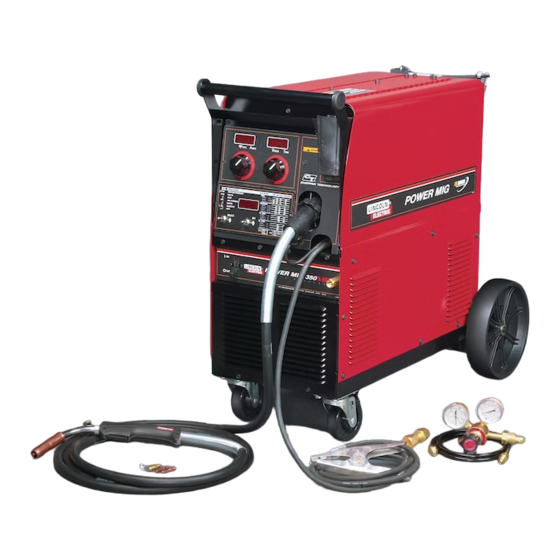
POWER MIG
350MP
January. 2006
™
For use with machine Code Number: 11147, 11309
For use with machine
Safety Depends on You
Lincoln arc welding and cutting
equipment is designed and built
with safety in mind. However, your
overall safety can be increased by
proper installation ... and thought-
ful operation on your part. DO
NOT INSTALL, OPERATE OR
REPAIR THIS EQUIPMENT
WITHOUT
READING
THIS
MANUAL AND THE SAFETY
PRECAUTIONS CONTAINED
THROUGHOUT. And, most
importantly, think before you act
and be careful.
SERVICE MANUAL
Copyright © 2006 Lincoln Global Inc.
• World's Leader in Welding and Cutting Products •
• Sales and Service through Subsidiaries and Distributors Worldwide •
Cleveland, Ohio 44117-1199 U.S.A. TEL: 216.481.8100 FAX: 216.486.1751 WEB SITE: www.lincolnelectric.com
Advertisement
Chapters
Table of Contents
Troubleshooting

Related Manuals for Lincoln Electric POWER MIG SVM165-A


Summary of Contents for Lincoln Electric POWER MIG SVM165-A
-
Page 1: Service Manual
RETURN TO MAIN MENU SVM165-A POWER MIG 350MP January. 2006 ™ For use with machine Code Number: 11147, 11309 For use with machine Safety Depends on You Lincoln arc welding and cutting equipment is designed and built with safety in mind. However, your overall safety can be increased by proper installation ... -
Page 2: Safety
351040, Miami, Florida 33135 or CSA Standard W117.2-1974. A Free copy of “Arc Welding Safety” booklet E205 is available from the Lincoln Electric Company, 22801 St. Clair Avenue, Cleveland, Ohio 44117-1199. BE SURE THAT ALL INSTALLATION, OPERATION, MAINTENANCE AND REPAIR PROCEDURES ARE PERFORMED ONLY BY QUALIFIED INDIVIDUALS. -
Page 3: Electric Shock Can Kill
ELECTRIC SHOCK can kill. 3.a. The electrode and work (or ground) circuits are electrically “hot” when the welder is on. Do not touch these “hot” parts with your bare skin or wet clothing. Wear dry, hole-free gloves to insulate hands. - Page 4 WELDING SPARKS can cause fire or explosion. 6.a. Remove fire hazards from the welding area. If this is not possible, cover them to prevent the welding sparks from starting a fire. Remember that welding sparks and hot materials from welding can easily go through small cracks and openings to adjacent areas.
- Page 5 PRÉCAUTIONS DE SÛRETÉ Pour votre propre protection lire et observer toutes les instructions et les précautions de sûreté specifiques qui parraissent dans ce manuel aussi bien que les précautions de sûreté générales suiv- antes: Sûreté Pour Soudage A L’Arc 1. Protegez-vous contre la secousse électrique: a.
-
Page 6: Table Of Contents
MASTER TABLE OF CONTENTS FOR ALL SECTIONS Safety...i-iv Installation ...Section A Operation...Section B Accessories...Section C Maintenance...Section D Theory of Operation...Section E Troubleshooting and Repair ...Section F How to Use Troubleshooting Guide...F-2 Troubleshooting Guide...F-4 Test Procedures ...F-14 Replacement Procedures ...F-36 Electrical Diagrams ...Section G Parts Manual...P512 Series RETURN TO MAIN MENU POWER MIG 350MP... - Page 7 TABLE OF CONTENTS - INSTALLATION SECTION - INSTALLATION...Section A Technical Specifications ...A-2 Safety Precautions...A-3 Input Supply Connection Diagram...A-4 Gun and Cable Installation...A-5 POWER MIG 350MP...
-
Page 8: Installation
TECHNICAL SPECIFICATIONS – POWER MIG 350MP Standard Voltage/Frequency 208/230/460/575/60 Hz Input Voltage Duty Cycle 230/460/575 208/230/460/575 100% Welding Current Range (Continuous) Maximum Open Circuit Voltage 5 – 350 Amps RECOMMENDED INPUT WIRE AND FUSE SIZES - SINGLE PHASE Input Voltage/ 230Amps @ Frequency (Hz) 29 Volts... -
Page 9: Safety Precautions
Roll the machine off the skid assembly. LOCATION Locate the welder in a dry location where there is free circulation of clean air into the louvers in the back and out the front. A location that minimizes the amount of... - Page 10 FIGURE A.1 — TRIPLE VOLTAGE MACHINE INPUT CONNECTIONS 3. The Power MIG is shipped with a 10ft.(3.05m) input cable and plug connected to the welder. Using the instructions in Figure A.2, have a qualified electri- cian connect the receptacle or cable to the input power lines and the system ground per the U.S.
-
Page 11: Gun And Cable Installation
.035-.045" (0.9-1.2 mm) electrode and contact tips for .035” (0.9mm) and .045” (1.2mm) are included for 15Ft.. WARNING Turn the welder power switch off before installing gun and cable. LINER INSTALLATION AND TRIMMING INSTRUCTION (SEE FIGURE A.3) 1. Remove the gas nozzle. - Page 12 DO NOT ATTACH THE REGULATOR IF OIL, GREASE OR DAMAGE IS PRESENT! Inform your gas supplier of this condition. Oil or grease in the presence of high pressure oxygen is explosive. 3. Stand to one side away from the outlet and open the cylinder valve for an instant.
- Page 13 TABLE OF CONTENTS - OPERATION SECTION - Operation...Section B Definitions of Welding Modes...B-2 Product Description ...B-3 Controls and Settings ...B-3/B-4 Setting and Configuring ...B-5 Multi-Process Panel Functions ...B-6 Arc Control...B-7 Wire Drive Roll ...B-8 Changing Drive and Idle Roll Sets ...B-9 Feeding Wire Electrode...B-10 Pulse Welding ...B-11 Pulse-On-Pulse...B-12...
-
Page 14: Operation
Read entire Operation section before operating the Power MIG 350MP. WARNING ELECTRIC SHOCK can kill. • Do not touch electrically live parts or electrode with skin or wet clothing. Insulate yourself from work and ground. • Always wear dry insulating gloves. -
Page 15: Product Description
PRODUCT DESCRIPTION The Power MIG 350MP is a complete semiautomatic multi-process DC arc welding machine offering CV and CC DC welding. It is rated for 350MP amps, 32 volts at a 60% duty cycle. The standard machine is equipped to weld CC-Stick, CC-GTAW, CV-FCAW, and synergic and non-synergic CV-GMAW / GMAW-P and Pulse-on-Pulse and Power Mode welding processes. - Page 16 2. VOLT / TRIM METER - This meter displays either the voltage or trim value depending on the status of the machine. Located below the display is the text "Volts" and "Trim." An LED light is illuminated to the left of one of these in order to indicate the units of the value displayed in the meter.
-
Page 17: Setting And Configuring
SETTING AND CONFIGURING THE POWER MIG 350MP FOR WELDING • Check that the electrode polarity is correct for the process and turn the Power Switch to the "ON" position. After the "boot-up" period (approximately 20 seconds), the Power MIG 350MP will default to the last preset weld mode that was active when the machine was powered down. -
Page 18: Multi-Process Panel Functions
MULTI-PROCESS PANEL FUNCTIONS Weld Mode Setting the Weld Mode is selecting the proper program from the ones available in the machine’s memory for a particular welding application. The table on the right side of the front panel (See Figure B.2) gives information on the different programs available in this machine. -
Page 19: Arc Control
Arc Control (See Table B.2) There are no specific unit values offered because the setting of this feature largely depends upon operator preference. Arc Control has a different effect on the character of the arc depending upon the welding process applied. In SMAW (STICK mode), arc control adjusts the arc force. -
Page 20: Wire Drive Roll
In the case of special waveforms designed for pulsed weld- ing aluminum, Pulse on Pulse™, the effect is similar to what occurs with standard pulse. As the Arc Control is increased from +1 to +10 the frequency of the Pulse on Pulse array increases. -
Page 21: Changing Drive And Idle Roll Sets
PROCEDURE FOR CHANGING DRIVE AND IDLE ROLL SETS 1. Turn off the power source. 2. Release the pressure on the idle roll by swinging the adjustable pressure arm down toward the back of the machine. Lift the cast idle roll assembly and allow it to sit in an upright position. -
Page 22: Feeding Wire Electrode
OPERATION 1. Press end of gun against a solid object that is elec- trically isolated from the welder output and press the gun trigger for several seconds. 2. If the wire “birdnests”, jams or breaks at the drive roll, the idle roll pressure is too great. -
Page 23: Pulse Welding
B-11 SPECIAL WELDING PROCESSES AVAILABLE ON THE POWER MIG 350MP PULSE WELDING (GMAW-P) The pulsed-arc process is, by definition, a spray trans- fer process wherein spray transfer occurs in pulses at regularly spaced intervals. In the time between pulses, the welding current is reduced and no metal transfer occurs. -
Page 24: Pulse-On-Pulse
Arc Control can be used to vary the ripple spacing in the weld bead. BENEFITS OF PULSE ON PULSE FROM LINCOLN ELECTRIC • Excellent appearance of the weld bead • Improved cleaning action • Reduced porosity Table B.3 shows WFS and Trim settings for common... -
Page 25: Power Mode
B-13 POWER MODE™ The Power Mode™ process was developed by Lincoln to maintain a stable and smooth arc at low procedure settings which are needed to weld thin metal without pop-outs or burning-through. For Aluminum welding, it provides excellent control and the ability to maintain constant arc length. - Page 26 NOTES B-14 B-14 POWER MIG 350MP...
-
Page 27: Accessories
TABLE OF CONTENTS - ACCESSORIES - Accessories...Section C Drive Roll Kits ...C-2 Push-Pull Feeding Connection Adapter Kit...C-3 POWER MIG 350MP... -
Page 28: Drive Roll Kits
DRIVE ROLL KITS Refer to Table C.1 for various drive roll kits that are available for the Power MIG. All items in Bold are supplied standard with the Power MIG. TABLE C.1 Wire Size .023”-.030” (0.6-0.8 mm) Solid .035” (0.9 mm) Steel .045”... -
Page 29: Push-Pull Feeding Connection Adapter Kit
ADAPTER KIT (K2154-1) The push-pull adapter kit provides direct connection of a Cobra Gold or Prince XL torch to the Power MIG wire feeder welder. 350MP The kit is intended for use with the following Cobra Gold or Prince XL torches:... - Page 30 NOTES POWER MIG 350MP...
-
Page 31: Maintenance
TABLE OF CONTENTS -MAINTENANCE- Maintenance...Section D Safety Precautions & General Maintenance ...D-2 Liner Removal and Replacement...D-3 POWER MIG 350MP... -
Page 32: Contact Tip And Gas Nozzle Installation
GENERAL MAINTENANCE In extremely dusty locations, dirt may clog the air pas- sages causing the welder to run hot. Blow dirt out of the welder with low-pressure air at regular intervals to eliminate excessive dirt and dust build-up on internal parts. -
Page 33: Liner Removal And Replacement
CAUTION Excessive pressure at the start may cause the dirt to form a plug. Flex the cable over its entire length and again blow out the cable. Repeat this procedure until no further dirt comes out. If this has been done and feed prob- lems are experienced, try liner replacement, and refer to trouble shooting section on rough wire feeding. - Page 34 MAINTENANCE 1. Case Front Assembly 2. Center Assembly 3. Wire Drive Assembly 4. Base Assembly 5. Case Back Assembly 6. Cover Assembly POWER MIG 350MP...
- Page 35 Section E-1 -THEORY OF OPERATION SECTION- Theory of Operation ...Section E General Description ...E-2 Input Voltage and Main Transformer ...E-3 Input Rectifier, Chopper Assembly and Feedback ...E-4 Diode Control Rectifier and Power Board ...E-5 Weld Control Board ...E-6 Wire Drive Motor and Feedback ...E-7 Thermal Protection, Over Current Protection, and Wire Feeder Overload Protection ...E-8 Insulated Gate Bipolar Transistor (IGBT) Operation ...E-9...
-
Page 36: Theory Of Operation
THEORY OF OPERATION FIGURE E.2 – GENERAL DESCRIPTION MAIN TRANSFORMER RECONNECT PANEL LINE SWITCH 115 VAC AUX. RECEPTACLE RELAY MOTOR FROM WELD CONTROL BOARD FOOT AMPTROL OR REMOTE (6-PIN AMPHENOL) 24 VDC SPOOL GUN OR PUSH-PULL GUN (7-PIN AMPHENOL) SOLENOID GENERAL DESCRIPTION The Power MIG 350MP is a complete semiautomatic, multi-process DC arc welding machine offering CV and... -
Page 37: Input Voltage And Main Transformer
THEORY OF OPERATION FIGURE E.3 – INPUT VOLTAGE AND MAIN TRANSFORMER TRANSFORMER RECONNECT PANEL LINE SWITCH 115 VAC AUX. RECEPTACLE RELAY MOTOR FROM WELD CONTROL BOARD FOOT AMPTROL OR REMOTE (6-PIN AMPHENOL) 24 VDC SPOOL GUN OR PUSH-PULL GUN (7-PIN AMPHENOL) SOLENOID INPUT VOLTAGE AND MAIN TRANS- FORMER... -
Page 38: Theory Of Operation
THEORY OF OPERATION FIGURE E.4 – OUTPUT RECTIFIER, CHOPPER ASSEMBLY AND FEEDBACK MAIN TRANSFORMER RECONNECT PANEL LINE SWITCH 115 VAC AUX. RECEPTACLE RELAY MOTOR FROM WELD CONTROL BOARD FOOT AMPTROL OR REMOTE (6-PIN AMPHENOL) 24 VDC SPOOL GUN OR PUSH-PULL GUN (7-PIN AMPHENOL) SOLENOID OUTPUT RECTIFIER,... -
Page 39: Diode Control Rectifier And Power Board
THEORY OF OPERATION FIGURE E.5 – DIODE CONTROL RECTIFIER AND POWER BOARD MAIN TRANSFORMER RECONNECT PANEL LINE SWITCH 115 VAC AUX. RECEPTACLE RELAY MOTOR FROM WELD CONTROL BOARD FOOT AMPTROL OR REMOTE (6-PIN AMPHENOL) 24 VDC SPOOL GUN OR PUSH-PULL GUN (7-PIN AMPHENOL) SOLENOID SOLENOID DIODE CONTROL RECTIFIER AND... -
Page 40: Weld Control Board
THEORY OF OPERATION FIGURE E.6 – WELD CONTROL BOARD TRANSFORMER RECONNECT PANEL LINE SWITCH 115 VAC AUX. RECEPTACLE RELAY MOTOR FROM WELD CONTROL BOARD FOOT AMPTROL OR REMOTE (6-PIN AMPHENOL) 24 VDC SPOOL GUN OR PUSH-PULL GUN (7-PIN AMPHENOL) SOLENOID WELD CONTROL BOARD The Weld Control Board performs the primary interfac- ing functions to establish and maintain output control of... -
Page 41: Wire Drive Motor And Feedback
THEORY OF OPERATION FIGURE E.7 – WIRE DRIVE MOTOR AND FEEDBACK TRANSFORMER RECONNECT PANEL LINE SWITCH RELAY MOTOR FROM WELD CONTROL BOARD FOOT AMPTROL OR REMOTE (6-PIN AMPHENOL) 24 VDC SPOOL GUN OR PUSH-PULL GUN (7-PIN AMPHENOL) WIRE DRIVE MOTOR AND FEED- BACK The Wire Drive Motor is controlled by the Feeder Board and the Weld Control Board. -
Page 42: Thermal Protection
THEORY OF OPERATION THERMAL PROTECTION Two normally closed (NC) thermostats protect the machine from excessive operating temperatures. These thermostats are wired in series and are con- nected to the Weld Control Board. One of the ther- mostats is located on the Chopper Assembly Board, and one is on the secondary of the Main Transformer. -
Page 43: Insulated Gate Bipolar Transistor (Igbt) Operation
THEORY OF OPERATION SOURCE DRAIN A. PASSIVE INSULATED GATE BIPOLAR TRANSISTOR (IGBT) OPERATION An IGBT is a type of transistor. IGBTs are semiconduc- tors well suited for high frequency switching and high current applications. Drawing A shows an IGBT in a passive mode. There is no gate signal, zero volts relative to the source, and therefore, no current flow. -
Page 44: Pulse Width Modulation
E-10 THEORY OF OPERATION FIGURE E.9 – TYPICAL IGBT OUTPUTS PULSE WIDTH MODULATION The term PULSE WIDTH MODULATION is used to describe how much time is devoted to conduction in the positive and negative portions of the cycle. Changing the pulse width is known as MODULATION. Pulse Width Modulation (PWM) is the varying of the pulse width over the allowed range of a cycle to affect the output of the machine. -
Page 45: Chopper Technology Fundamentals
E-11 THEORY OF OPERATION CHOPPER TECHNOLOGY FUNDAMENTALS The new era of welding machines such as the Power MIG 350MP employ a technology whereby a DC source is turned on and off (chopped up) at high speed, then smoothed through an inductor to control an arc. Hence the name “Chopper.”... - Page 46 E-12 E-12 NOTES POWER MIG 350MP...
- Page 47 Section F-1 TROUBLESHOOTING & REPAIR SECTION Troubleshooting & Repair Section ...Section F How to Use Troubleshooting Guide ...F-2 PC Board Troubleshooting Procedures ...F-3 Troubleshooting Guide ...F-4 - F-15 Chopper Board Capacitor Discharge Procedure ...F-16 Main Transformer Test ...F-18 Chopper Board Test ...F-20 Control Rectifier Test ...F-23 Output Rectifier Assembly Test ...F-25 Wire Drive Motor and Tachometer Feedback Test ...F-27...
-
Page 48: Troubleshooting And Repair
TROUBLESHOOTING & REPAIR HOW TO USE TROUBLESHOOTING GUIDE Service and repair should be performed by only Lincoln Electric Factory Trained Personnel. Unauthorized repairs performed on this equipment may result in danger to the technician and machine operator and will invalidate your factory warranty. For your safety and to avoid Electrical Shock, please observe all safety notes and precautions detailed throughout this manual. -
Page 49: Pc Board Troubleshooting Procedures
- If the PC Board uses protective shorting jumpers, don’t remove them until installation is complete. - If you return a PC Board to The Lincoln Electric Company for credit, it must be in the static-shielding bag. This will prevent further damage and allow prop- er failure analysis. -
Page 50: Troubleshooting Guide
If for any reason you do not understand the test procedures or are unable to perform the test/repairs safely, contact the Lincoln Electric Service Department for electrical troubleshooting assistance before you proceed. Call 1-888-935-3877. POSSIBLE AREAS OF... - Page 51 If for any reason you do not understand the test procedures or are unable to perform the test/repairs safely, contact the Lincoln Electric Service Department for electrical troubleshooting assistance before you proceed. Call 1-888-935-3877.
- Page 52 The wire is not feeding. If for any reason you do not understand the test procedures or are unable to perform the test/repairs safely, contact the Lincoln Electric Service Department for electrical troubleshooting assistance before you proceed. Call 1-888-935-3877.
- Page 53 115VAC receptacle. If for any reason you do not understand the test procedures or are unable to perform the test/repairs safely, contact the Lincoln Electric Service Department for electrical troubleshooting assistance before you proceed. Call 1-888-935-3877. detailed in the beginning of this manual.
- Page 54 The machine stops feeding wire while welding. If for any reason you do not understand the test procedures or are unable to perform the test/repairs safely, contact the Lincoln Electric Service Department for electrical troubleshooting assistance before you proceed. Call 1-888-935-3877. POSSIBLE AREAS OF...
- Page 55 If for any reason you do not understand the test procedures or are unable to perform the test/repairs safely, contact the Lincoln Electric Service Department for electrical troubleshooting assistance before you proceed. Call 1-888-935-3877. detailed in the beginning of this manual.
- Page 56 The arc striking is poor. If for any reason you do not understand the test procedures or are unable to perform the test/repairs safely, contact the Lincoln Electric Service Department for electrical troubleshooting assistance before you proceed. Call 1-888-935-3877. POSSIBLE AREAS OF...
- Page 57 If for any reason you do not understand the test procedures or are unable to perform the test/repairs safely, contact the Lincoln Electric Service Department for electrical troubleshooting assistance before you proceed. Call 1-888-935-3877. POSSIBLE AREAS OF MISADJUSTMENT(S) 1.
- Page 58 If for any reason you do not understand the test procedures or are unable to perform the test/repairs safely, contact the Lincoln Electric Service Department for electrical troubleshooting assistance before you proceed. Call 1-888-935-3877. POSSIBLE AREAS OF MISADJUSTMENT(S) 1.
- Page 59 Wire bird nests while welding. If for any reason you do not understand the test procedures or are unable to perform the test/repairs safely, contact the Lincoln Electric Service Department for electrical troubleshooting assistance before you proceed. Call 1-888-935-3877. POSSIBLE AREAS OF MISADJUSTMENT(S) 1.
- Page 60 PUSH PULL WIRE FEEDING PROBLEMS STALL FACTOR - an adjustment to the Power Mig 350MP that allows the welder to adjust the maximum amount of power going to the rear drive motor. The purpose is to send only enough power to the rear drive motor to pull the wire off the spool and get the wire up the torch liner.
- Page 61 --------- Scrolling dashes If for any reason you do not understand the test procedures or are unable to perform the test/repairs safely, contact the Lincoln Electric Service Department for electrical troubleshooting assistance before you proceed. Call 1-888-935-3877. TROUBLESHOOTING GUIDE CORRECTIVE...
-
Page 62: Chopper Board Capacitor Discharge Procedure
TROUBLESHOOTING & REPAIR CHOPPER BOARD CAPACITOR DISCHARGE PROCEDURE Service and repair should be performed by only Lincoln Electric factory trained personnel. Unauthorized repairs performed on this equipment may result in danger to the technician or machine operator and will invalidate your factory warranty. For your safety and to avoid electrical shock, please observe all safety notes and precautions detailed throughout this manual. - Page 63 F-17 TROUBLESHOOTING & REPAIR CHOPPER BOARD CAPACITOR DISCHARGE PROCEDURE (continued) FIGURE F.1 – CHOPPER BOARD CAPACITOR TERMINAL DISCHARGE PROCEDURE WARNING ELECTRIC SHOCK can kill. High voltage is present when input power is applied to the machine. Refer to Figure F.1. 1.
-
Page 64: Main Transformer Test
TROUBLESHOOTING & REPAIR MAIN TRANSFORMER TEST Service and repair should be performed by only Lincoln Electric factory trained personnel. Unauthorized repairs performed on this equipment may result in danger to the technician or machine operator and will invalidate your factory warranty. For your safety and to avoid electrical shock, please observe all safety notes and precautions detailed throughout this manual. - Page 65 F-19 TROUBLESHOOTING & REPAIR MAIN TRANSFORMER TEST (continued) FIGURE F.2 – MAIN TRANSFORMER TEST POINT LOCATIONS (SHOWN CONNECTED FOR 230V) RECONNECT PANEL PROCEDURE WARNING The ON/OFF POWER SWITCH will be "hot" during these tests. NOTE: Secondary voltages will vary proportionately with the primary input voltage.
-
Page 66: Chopper Board Test
F-20 TROUBLESHOOTING & REPAIR Service and repair should be performed by only Lincoln Electric factory trained personnel. Unauthorized repairs performed on this equipment may result in danger to the technician or machine operator and will invalidate your factory warranty. For your safety and to avoid electrical shock, please observe all safety notes and precautions detailed throughout this manual. - Page 67 F-21 TROUBLESHOOTING & REPAIR CHOPPER BOARD TEST (continued) TEST PROCEDURE 1. Disconnect the main AC input power to the machine. 2. Remove the case side panels with a 3/8” nut driver. 3. Locate plug J99. (Later machine do not have J99). 4.
- Page 68 F-22 TROUBLESHOOTING & REPAIR CHOPPER BOARD TEST (continued) PWM SIGNAL TEST 1. Locate 607 (7J6) and 615 (15J6) on the control board. See Figure F.4. 2. Perform the following voltage test or hertz read- ings when the trigger is pulled. To Lead From Lead (7J6)
-
Page 69: Control Rectifier Test
TROUBLESHOOTING & REPAIR CONTROL RECTIFIER TEST Service and repair should be performed by only Lincoln Electric factory trained personnel. Unauthorized repairs performed on this equipment may result in danger to the technician or machine operator and will invalidate your factory warranty. For your safety and to avoid elec- trical shock, please observe all safety notes and precautions detailed throughout this manual. - Page 70 F-24 TROUBLESHOOTING & REPAIR CONTROL RECTIFIER TEST (continued) TEST PROCEDURE 1. Find the following leads at the control rectifier using figures F.5 and F.6. From Lead Expected Voltage To Lead 471B 472B FIGURE F.5 115 VAC 30 VAC CONTROL RECTIFIER LOCATED ON TRANSFORMER BAFFLE...
-
Page 71: Output Rectifier Assembly Test
TROUBLESHOOTING & REPAIR OUTPUT RECTIFIER ASSEMBLY TEST Service and repair should be performed by only Lincoln Electric factory trained personnel. Unauthorized repairs performed on this equipment may result in danger to the technician or machine operator and will invalidate your factory warranty. For your safety and to avoid electrical shock, please observe all safety notes and precautions detailed throughout this manual. - Page 72 F-26 TROUBLESHOOTING & REPAIR OUTPUT RECTIFIER ASSEMBLY TEST (continued) FIGURE F.7– OUTPUT RECTIFIER ASSEMBLY LOCATION TEST PROCEDURE 1. Disconnect the main AC input power to the machine. 2. Perform the Chopper Assembly Capacitor Discharge procedure. 3. Locate and disconnect the negative lead from the output rectifier bridge assembly.
- Page 73 TROUBLESHOOTING & REPAIR WIRE DRIVE MOTOR AND TACHOMETER FEEDBACK Service and repair should be performed by only Lincoln Electric factory trained personnel. Unauthorized repairs performed on this equipment may result in danger to the technician or machine operator and will invalidate your factory warranty. For your safety and to avoid electrical shock, please observe all safety notes and precautions detailed throughout this manual.
-
Page 74: Wire Drive Motor And Tachometer Feedback Test
F-28 TROUBLESHOOTING & REPAIR WIRE DRIVE MOTOR AND TACHOMETER FEEDBACK TEST (continued) FIGURE F. 8 – PLUG J83 AND J84 LOCATIONS ON FEEDER BOARD G3884 TEST PROCEDURE NOTE: POLARITY MUST BE OBSERVED FOR THESE TESTS. TEST FOR CORRECT WIRE DRIVE MOTOR ARMA- TURE VOLTAGE 1. - Page 75 F-29 TROUBLESHOOTING & REPAIR WIRE DRIVE MOTOR AND TACHOMETER FEEDBACK TEST (continued) TEST SUPPLY VOLTAGE TACHOMETER AND FEEDBACK VOLTAGE 1. Locate the following leads on Plug J84. Leads 841 (1J84) and 844 (4J84) \2. Make the following voltage tests. From the table below.
-
Page 76: Encoder Pc Board Test (10562 & Above
TROUBLESHOOTING & REPAIR ENCODER PC BOARD TEST Service and repair should be performed by only Lincoln Electric factory trained personnel. Unauthorized repairs performed on this equipment may result in danger to the technician or machine operator and will invalidate your factory warranty. For your safety and to avoid elec- trical shock, please observe all safety notes and precautions detailed throughout this manual. - Page 77 F-31 TROUBLESHOOTING & REPAIR ENCODER PC BOARD TEST (continued) FIGURE F. 9 - FEEDHEAD P.C. BOARD 3243 TEST PROCEDURE 1. Disconnect the main AC input power to the machine. 2. Locate the following leads on Plug J85 and J86 located on the feedhead P.C. Board. See Figure F.9.
- Page 78 F-32 TROUBLESHOOTING & REPAIR ENCODER PC BOARD TEST (continued) VOLT/TRIM ENCODER #1 FROM LEAD TO LEAD EXPECTED VOLTAGE 3243 5J85 3J82 8511 3243 11J85 3J82 3243 8J85 3J82 WMF/AMPS ENCODER #2 FROM LEAD TO LEAD EXPECTED VOLTAGE 3243 9J85 3J82 3243 7J85 3J82...
-
Page 79: Current Transducer Test
TROUBLESHOOTING & REPAIR CURRENT TRANSDUCER TEST Service and repair should be performed by only Lincoln Electric factory trained personnel. Unauthorized repairs performed on this equipment may result in danger to the technician or machine operator and will invalidate your factory warranty. For your safety and to avoid elec- trical shock, please observe all safety notes and precautions detailed throughout this manual. - Page 80 F-34 TROUBLESHOOTING & REPAIR CURRENT TRANSDUCER TEST (continued) TEST PROCEDURE 1. Remove input power to the machine 2. Remove the left case side of the machine. 3. Remove the PC Board compartment door. 4. Locate plug J8 at the Control Board. See Figure F.10.
- Page 81 F-35 TROUBLESHOOTING & REPAIR CURRENT TRANSDUCER TEST (continued) Table F.2 – Current Transducer Feedback Voltage OUTPUT LOAD CURRENT EXPECTED TRANSDUCER FEEDBACK VOLTAGE POWER MIG 350MP F-35...
-
Page 82: Power Mig Scrolling Dashes Test
POWER MIG 350MP SCROLLING DASHES TEST WARNING Service and repair should be performed by only Lincoln Electric factory trained personnel. Unauthorized repairs performed on this equipment may result in danger to the technician or machine operator and will invalidate your factory warranty. For your safety and to avoid elec- trical shock, please observe all safety notes and precautions detailed throughout this manual. -
Page 83: Test Procedures
F-37 TROUBLESHOOTING & REPAIR POWER MIG 350MP SCROLLING DASHES TEST (continued) TEST PROCEDURES: 1. Hold “select” switch up while powering up machine. 2. Release “select” switch when displays show “PrESSPin”. 3. Turn the right “encoder knob” until displays show “CLrAll”. 4. -
Page 84: Oscilloscope Waveforms
F-38 TROUBLESHOOTING & REPAIR OSCILLOSCOPE WAVEFORMS MUST BE TAKEN IN MODE 201 NORMAL OPEN CIRCUIT VOLTAGE WAVEFORM 20.0 V This is a typical DC output voltage waveform generated from a properly operating machine. Note that each vertical division represents 20 volts and that each horizontal division represents 2.00 milliseconds in time. - Page 85 F-39 TROUBLESHOOTING & REPAIR TYPICAL OUTPUT VOLTAGE WAVEFORM - MACHINE LOADED MACHINE LOADED TO 250 AMPS AT 26 VDC 20.0 V This is a typical DC output voltage waveform generated from a properly operating machine. Note that each vertical division represents 20 volts and that each horizontal division represents 2.00 milliseconds in time.
- Page 86 TROUBLESHOOTING & REPAIR MOTOR & GEAR BOX ASSEMBLY REMOVAL AND Service and repair should be performed by only Lincoln Electric factory trained personnel. Unauthorized repairs performed on this equipment may result in danger to the technician or machine operator and will invalidate your factory warranty. For your safety and to avoid electrical shock, please observe all safety notes and precautions detailed throughout this manual.
-
Page 87: Removal And Replacement Procedures
F-41 TROUBLESHOOTING & REPAIR MOTOR & GEAR BOX ASSEMBLY REMOVAL AND REPLACEMENT (continued) REMOVAL PROCEDURE WARNING ELECTRIC SHOCK can kill. High voltage is present when input power is applied to the machine. 1. Disconnect main input power to the machine. 2. - Page 88 F-42 TROUBLESHOOTING & REPAIR MOTOR & GEAR BOX ASSEMBLY REMOVAL AND REPLACEMENT (continued) REPLACEMENT PROCEDURE 1. Bolt the wire drive assembly to the wire drive compartment. 2. Secure the wire drive compartment to the divider panel welded assembly. 3. Mount the motor/gearbox assembly to the wire drive assembly and attach with screws.
- Page 89 F-43 F-43 TROUBLESHOOTING & REPAIR MOTOR & GEAR BOX ASSEMBLY REMOVAL AND REPLACEMENT (continued) FIGURE F.11 POWER MIG 350MP...
-
Page 90: Output Rectifier Removal And Replacement
TROUBLESHOOTING & REPAIR REMOVAL AND REPLACEMENT Service and repair should be performed by only Lincoln Electric factory trained personnel. Unauthorized repairs performed on this equipment may result in danger to the technician or machine operator and will invalidate your factory warranty. For your safety and to avoid elec- trical shock, please observe all safety notes and precautions detailed throughout this manual. - Page 91 F-45 TROUBLESHOOTING & REPAIR REMOVAL AND REPLACEMENT (continued) WARNING ELECTRIC SHOCK can kill. High voltage is present when input power is applied to the machine. Note: Cut cable ties as needed to improve access. See Figure F.12 for the following procedure. 1.
- Page 92 F-46 TROUBLESHOOTING & REPAIR REMOVAL AND REPLACEMENT (continued) washers holding the rectifier bracket to the machine base. 10. Clear the leads and carefully remove the output rectifier assembly. 11. With a 1/2” wrench, loosen the 3 nuts holding the rectifier to its bracket. REPLACEMENT PROCEDURE NOTE: When installing the output rectifier assembly, apply a thin coating of Dow Corning #340 com-...
- Page 93 TROUBLESHOOTING & REPAIR CHOPPER BOARD ASSEMBLY REMOVAL Service and repair should be performed by only Lincoln Electric factory trained personnel. Unauthorized repairs performed on this equipment may result in danger to the technician or machine operator and will invalidate your factory warranty. For your safety and to avoid elec- trical shock, please observe all safety notes and precautions detailed throughout this manual.
- Page 94 F-48 TROUBLESHOOTING & REPAIR CHOPPER BOARD ASSEMBLY REMOVAL AND REPLACEMENT (continued) FIGURE F.13 – CHOPPER BOARD ASSEMBLY DETAILS REMOVAL PROCEDURE WARNING ELECTRIC SHOCK can kill. High voltage is present when input power is applied to the machine. Note: Cut cable ties as needed to improve access. See Figure F.13 for the following procedure.
-
Page 95: Chopper Board Assembly Removal And Replacement
F-49 TROUBLESHOOTING & REPAIR CHOPPER BOARD ASSEMBLY REMOVAL AND REPLACEMENT (continued) REPLACEMENT PROCEDURE 1. Attach the chopper assembly brackets to the new chopper assembly. 2. Install the chopper board assembly. Fasten it to the machine base with 4 lock washers and nuts. 3. -
Page 96: Main Transformer And Output Choke Removal And Replacement
TROUBLESHOOTING & REPAIR MAIN TRANSFORMER AND OUTPUT CHOKE REMOVAL AND Service and repair should be performed by only Lincoln Electric factory trained personnel. Unauthorized repairs performed on this equipment may result in danger to the technician or machine operator and will invalidate your factory warranty. For your safety and to avoid elec- trical shock, please observe all safety notes and precautions detailed throughout this manual. - Page 97 F-51 TROUBLESHOOTING & REPAIR MAIN TRANSFORMER AND OUTPUT CHOKE REMOVAL AND REPLACE- REMOVAL PROCEDURE WARNING ELECTRIC SHOCK can kill. High voltage is present when input power is applied to the machine. Note: Cut cable ties as needed to improve access. PREPARATION 1.
- Page 98 F-52 TROUBLESHOOTING & REPAIR MAIN TRANSFORMER AND OUTPUT CHOKE REMOVAL AND REPLACE- LEAD DISCONNECTION 8. Using a phillips head screwdriver, remove fan lead X4 from fan relay terminal #1 and disconnect fan lead X3 from its in-line connector at the fan motor. Cut cable ties as needed pull the leads through the baffles to clear them.
- Page 99 F-53 TROUBLESHOOTING & REPAIR MAIN TRANSFORMER AND OUTPUT CHOKE REMOVAL AND REPLACE- BACK BACK SIDE SIDE (10) (10) BACK BACK SIDE SIDE MENT (continued) FIGURE F.14 UNDER UNDER PANEL PANEL POWER MIG 350MP F-53 11 11...
-
Page 100: Fan Motor Assembly Removal And Replacement
TROUBLESHOOTING & REPAIR FAN MOTOR ASSEMBLY REMOVAL AND REPLACEMENT Service and repair should be performed by only Lincoln Electric factory trained personnel. Unauthorized repairs performed on this equipment may result in danger to the technician or machine operator and will invalidate your factory warranty. For your safety and to avoid elec- trical shock, please observe all safety notes and precautions detailed throughout this manual. - Page 101 F-55 TROUBLESHOOTING & REPAIR FAN MOTOR ASSEMBLY REMOVAL AND REPLACEMENT FIGURE F.15 – FAN MOTOR ASSEMBLY REMOVAL REMOVAL PROCEDURE 1. Disconnect main input power to the machine. 2. Remove the case side panels using a 3/8” nut dri- ver. 3. Cut the wire tie from around the fan motor leads. 4.
-
Page 102: Voltage & Current Calibration Procedure
TROUBLESHOOTING & REPAIR VOLTAGE & CURRENT CALIBRATION PROCEDURE Service and repair should be performed by only Lincoln Electric factory trained personnel. Unauthorized repairs performed on this equipment may result in danger to the technician or machine operator and will invalidate your factory warranty. For your safety and to avoid elec- trical shock, please observe all safety notes and precautions detailed throughout this manual. - Page 103 F-57 TROUBLESHOOTING & REPAIR VOLTAGE & CURRENT CALIBRATION PROCEDURE (continued) CALIBRATION CHECK The calibration of the Power MIG 350MP can be checked using a resistive load bank with the Power MIG 350MP in mode 200. Mode 200 is a constant current test mode. 1.
- Page 104 F-58 TROUBLESHOOTING & REPAIR VOLTAGE & CURRENT CALIBRATION PROCEDURE (continued) 9. Wait for the machine’s output to be automati- cally turned off and then back on. 10. Adjust the output control knob again if neces- sary to make the actual voltage output 20 volts +/- .5 volts.
-
Page 105: Retest After Repair
F-59 TROUBLESHOOTING & REPAIR Retest a machine: • If it is rejected under test for any reason that requires you to remove any part which could affect the machine’s electrical characteristics. • If you repair or replace any electrical components. Input Volts/Hertz 230/60 AMPS... - Page 106 F-60 F-60 NOTES POWER MIG 350MP...
- Page 107 ELECTRICAL DIAGRAMS -ELECTRICAL DIAGRAMS SECTION- ELECTRICAL DIAGRAMS ............SECTION G WIRING DIAGRAM (G4678) .
-
Page 108: Section E
WIRING DIAGRAM - ENTIRE MACHINE G4678 ENGINEERING CONTROLLED CHANGE DETAIL: RELEASED A.03 FROM X. MANUFACTURER: DISPLAY MS P III CONTROL BOARD BOARD BOARD FLEX CIRCUIT SHIELDED CABLE P.C. BOARD CONNECTION DETAIL H5 H2 H3 H4 (SHOWN CONNECTED FOR 230V) RECONNECT PANEL MSP III BOARD SELECT 3411... - Page 109 SCHEMATIC - ENTIRE MACHINE G4677 ENGINEERING CONTROLLED CHANGE DETAIL: RELEASED A.02 FROM X. MANUFACTURER: LOCATED ON FRONT OF MACHINE'S BASE MAIN TRANSFORMER LOCATED ON MACHINE'S BASE (STORAGE COMPARTMENT SIDE) (SHOWN CONNECTED FOR 230V) LINE SWITCH RECONNECT PANEL 57 VAC 115 VAC 30 VAC DIODE RECTIFIER 115V...
- Page 110 ELECTRICAL DIAGRAMS SCHEMATIC - CONTROL PC BOARD (G3789-1E2/1) NOTE: This diagram is for reference only. It may not be accurate for all machines covered by this manual. POWER MIG 350MP...
- Page 111 ELECTRICAL DIAGRAMS SCHEMATIC - CONTROL PC BOARD (G3789-1E2/2) NOTE: This diagram is for reference only. It may not be accurate for all machines covered by this manual. POWER MIG 350MP...
- Page 112 ELECTRICAL DIAGRAMS SCHEMATIC - CONTROL PC BOARD (G3789-1E2/3) NOTE: This diagram is for reference only. It may not be accurate for all machines covered by this manual. POWER MIG 350MP...
- Page 113 ELECTRICAL DIAGRAMS SCHEMATIC - CONTROL PC BOARD (G3789-1E2/4) NOTE: This diagram is for reference only. It may not be accurate for all machines covered by this manual. POWER MIG 350MP...
- Page 114 Lincoln Electric discourages board level troubleshooting and repair since it may compromise the quality of the design and may result in danger to the Machine Operator or Technician.
- Page 115 ELECTRICAL DIAGRAMS SCHEMATIC POWER SUPPLY P.C. BOARD (G3631-3F0) NOTE: This diagram is for reference only. It may not be accurate for all machines covered by this manual. POWER MIG 350MP...
- Page 116 Lincoln Electric discourages board level troubleshooting and repair since it may compromise the quality of the design and may result in danger to the Machine Operator or Technician.
- Page 117 G-11 G-11 ELECTRICAL DIAGRAMS SCHEMATIC - CHOPPER P.C. BOARD (M20046-1M0) NOTE: This diagram is for reference only. It may not be accurate for all machines covered by this manual. POWER MIG 350MP...
- Page 118 Lincoln Electric discourages board level troubleshooting and repair since it may compromise the quality of the design and may result in danger to the Machine Operator or Technician.
- Page 119 G-13 G-13 ELECTRICAL DIAGRAMS SCHEMATIC - MSP3 PC BOARD (L11612-2D0) NOTE: This diagram is for reference only. It may not be accurate for all machines covered by this manual. POWER MIG 350MP...
- Page 120 Lincoln Electric discourages board level troubleshooting and repair since it may compromise the quality of the design and may result in danger to the Machine Operator or Technician.
- Page 121 G-15 G-15 ELECTRICAL DIAGRAMS SCHEMATIC - FEEDER P.C. BOARD (G3883-1E0/1) NOTE: This diagram is for reference only. It may not be accurate for all machines covered by this manual. POWER MIG 350MP...
- Page 122 G-16 G-16 ELECTRICAL DIAGRAMS SCHEMATIC - FEEDER P.C. BOARD (G3883-1E0/2) NOTE: This diagram is for reference only. It may not be accurate for all machines covered by this manual. POWER MIG 350MP...
- Page 123 Lincoln Electric discourages board level troubleshooting and repair since it may compromise the quality of the design and may result in danger to the Machine Operator or Technician.
- Page 124 G-18 G-18 ELECTRICAL DIAGRAMS SCHEMATIC - SPOOL GUN P.C. BOARD (L12008-2D0) NOTE: This diagram is for reference only. It may not be accurate for all machines covered by this manual. POWER MIG 350MP...
- Page 125 Lincoln Electric discourages board level troubleshooting and repair since it may compromise the quality of the design and may result in danger to the Machine Operator or Technician.
- Page 126 G-20 G-20 ELECTRICAL DIAGRAMS SCHEMATIC - DISPLAY P.C. BOARD (L11756-1E1) NOTE: This diagram is for reference only. It may not be accurate for all machines covered by this manual. POWER MIG 350MP...
- Page 127 Lincoln Electric discourages board level troubleshooting and repair since it may compromise the quality of the design and may result in danger to the Machine Operator or Technician.
- Page 128 Your Company__________________________ Your Name_____________________________ Please give detailed description below: ___________________________________________________________________________ ___________________________________________________________________________ ___________________________________________________________________________ ___________________________________________________________________________ ___________________________________________________________________________ ___________________________________________________________________________ ___________________________________________________________________________ ___________________________________________________________________________ ___________________________________________________________________________ ___________________________________________________________________________ ___________________________________________________________________________ ___________________________________________________________________________ ___________________________________________________________________________ SD287 01/99 Thank You, Technical Services Group Lincoln Electric Co. 22801 ST. Clair Ave. Cleveland, Ohio 44117-1199 FAX 216-481-2309...